Three-dimensional NoC noise model and simulating method thereof
A simulation system and noise technology, applied in special data processing applications, instruments, electrical digital data processing, etc., can solve the problems of not considering the power distribution network of the system, and the influence of noise cannot be simulated, so as to solve the problem that the influence of noise cannot be simulated and improve Effects of Simulation Accuracy
- Summary
- Abstract
- Description
- Claims
- Application Information
AI Technical Summary
Problems solved by technology
Method used
Image
Examples
Embodiment 1
[0054] In Embodiment 1, the metal lines of the upper, middle and lower layers are parallel lines.
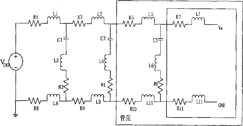
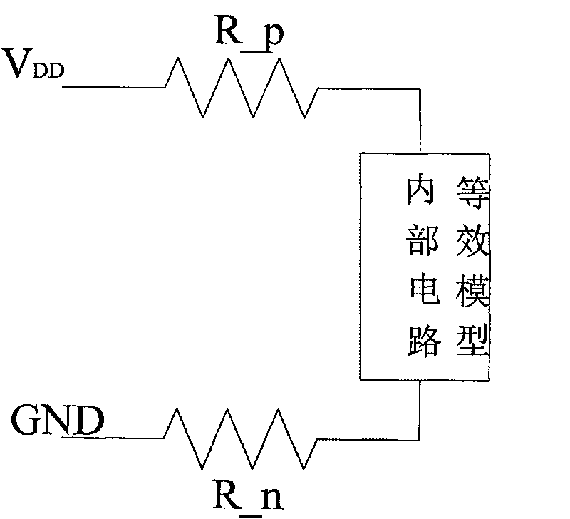
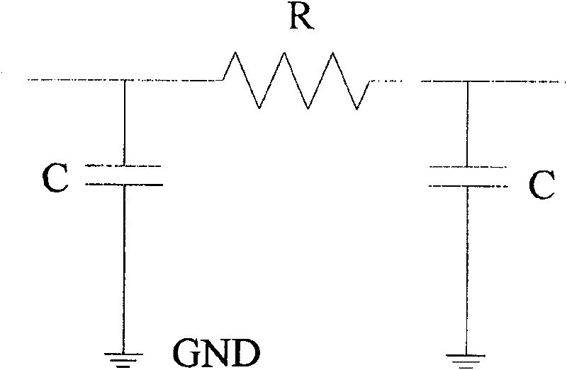
[0055] Such as figure 1 , figure 2 , image 3 , Figure 4 with Image 6 As shown, INV_* (where * is a number) in the model is an inverter model, which has 4 pins: power supply V DD , ground GND, input pins and output pins. In the model, an inverter is used to drive a wire, followed by an inverter to simulate the driving relationship. exist Image 6 The disturbed line is the signal line driven by INV_23, and the disturbed line is the signal line driven by INV_11, INV_13, INV_15, INV_21, INV_25, INV_31, INV_33, and INV_35. Two equivalent capacitances across the junction between two π models are used in the model to simulate crosstalk effects.
[0056] Since the power distribution network of the system is located at the outermost layer and its main function is to provide power for the system, the equivalent model of the power supply package should also be located at the ou...
Embodiment 2
[0068] Embodiment 2 is described by taking an example in which the upper and lower layers of wires are perpendicular to the middle layer of wires.
[0069] Such as figure 1 , figure 2 , image 3 , Figure 5 with Figure 7 As shown, INV_* (where * is a number) in the model is an inverter model, which has 4 pins: power supply V DD , ground GND, input pins and output pins. In the model, an inverter is used to drive a wire, followed by an inverter to simulate the driving relationship. The upper wire is modeled with a 2-segment π model, and the middle wire is modeled with a 1-segment π model. The underlying wires are modeled with a 2-segment π model. exist Figure 7 The disturbed line is the signal line driven by INV_23, and the disturbed line is the signal line driven by INV_11, INV_13, INV_21, INV_25, INV_31, and INV_33. Two equivalent capacitances across the junction between two π models are used in the model to simulate crosstalk effects.
[0070] Since the power dist...
PUM
 Abstract
Description
Claims
Application Information
 - Generate Ideas
- Intellectual Property
- Life Sciences
- Materials
- Tech Scout
- Unparalleled Data Quality
- Higher Quality Content
- 60% Fewer Hallucinations
Browse by: Latest US Patents, China's latest patents, Technical Efficacy Thesaurus, Application Domain, Technology Topic, Popular Technical Reports.
© 2025 PatSnap. All rights reserved.Legal|Privacy policy|Modern Slavery Act Transparency Statement|Sitemap|About US| Contact US: help@patsnap.com


