Pen clip for writing tool

A writing tool and pen clip technology, applied in the field of writing tool clips, can solve the problems of writing tools falling off, poor pressing state, easy plastic deformation, etc., and achieve the effect of good installability

Inactive Publication Date: 2009-02-11
TOMBOW PENCIL CO LTD
View PDF2 Cites 0 Cited by
  • Summary
  • Abstract
  • Description
  • Claims
  • Application Information

AI Technical Summary

Problems solved by technology

[0004] However, in the clips described in the aforementioned Patent Documents 1 and 2, only the lower end base of the clip body, which is bent and formed into a U-shape when viewed from the front, is used to elastically clamp the clamped object such as a clothes pocket. Poor and slippery, therefore, the writing instrument is not only easy to fall out of the pocket, but also has poor functionality and appearance
[0005] Therefore, in order to eliminate the above-mentioned undesirable phenomenon, if the pen holder is installed at the lower end base of the pen holder body, between the left and right wire rods of the pen holder body, there is a desired separation between the left and right wire rods through the bending process of the wire rods. The angle is provided with spring elasticity when attached to the main body of the writing instrument, but the separation angle varies greatly for each clip-bent product, and there are various processings for the bent wire according to the type of metal. characteristics, so it is easy to plastically deform, and since the stable shape as designed cannot be obtained, it is difficult to stably install the pen clip at the same position on the lower end base of the clip body
[0006] Moreover, when the clip body is installed on the writing instrument body, due to the difference in spring elasticity caused by the difference in the separation angle between the left and right wires, the clip body has poor mountability relative to the writing instrument body and cannot be installed stably. The problem

Method used


Image

  • Pen clip for writing tool
  • Pen clip for writing tool
  • Pen clip for writing tool

Examples


Embodiment Construction

[0048] Hereinafter, embodiments of the present invention will be described in detail with reference to the drawings.

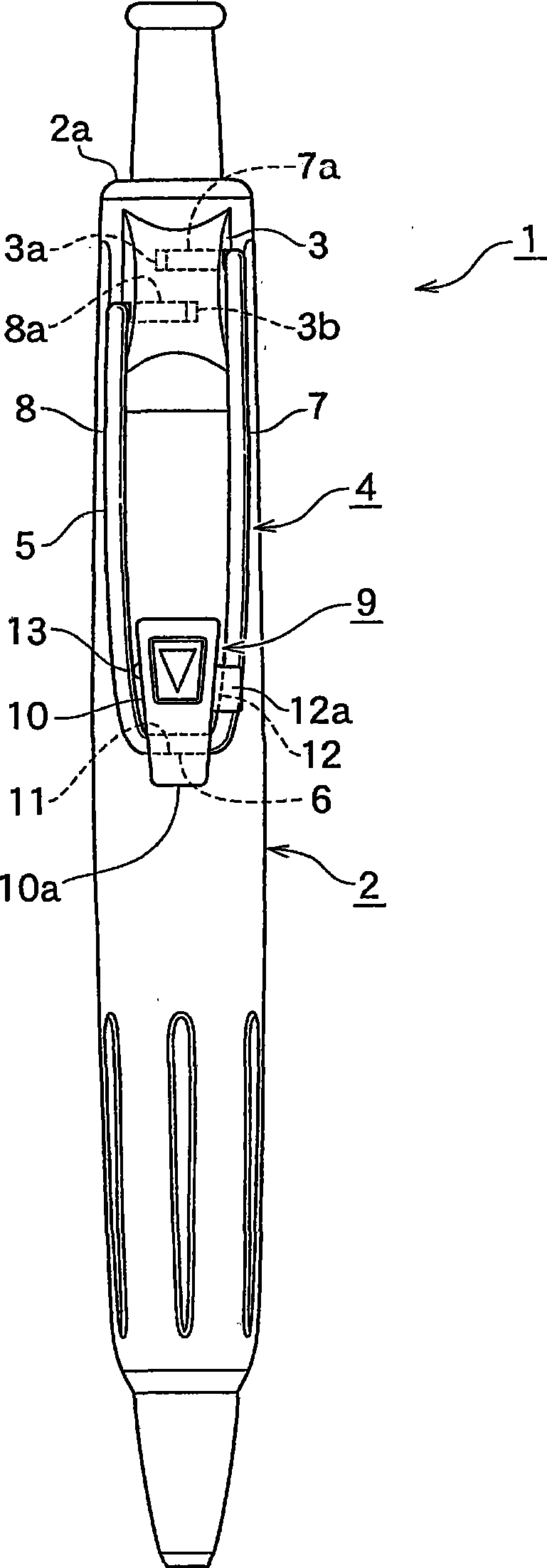
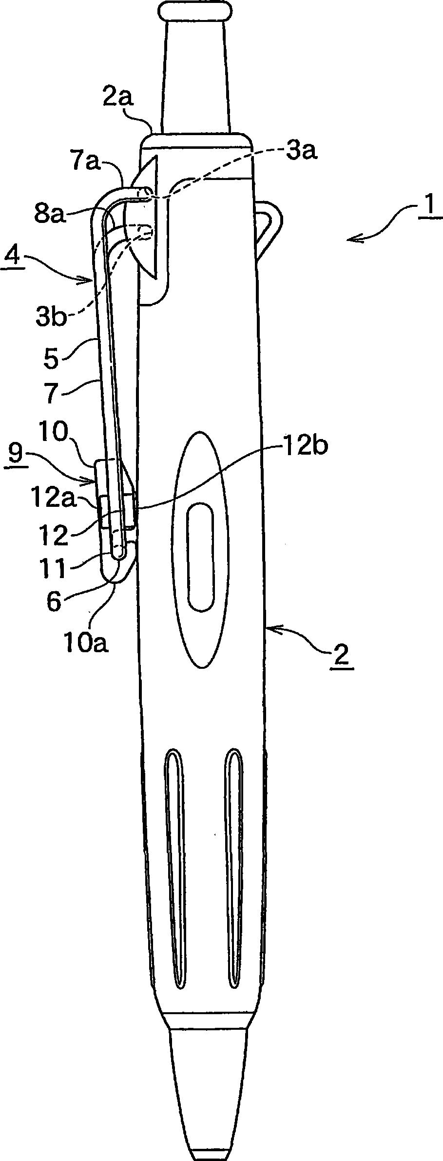
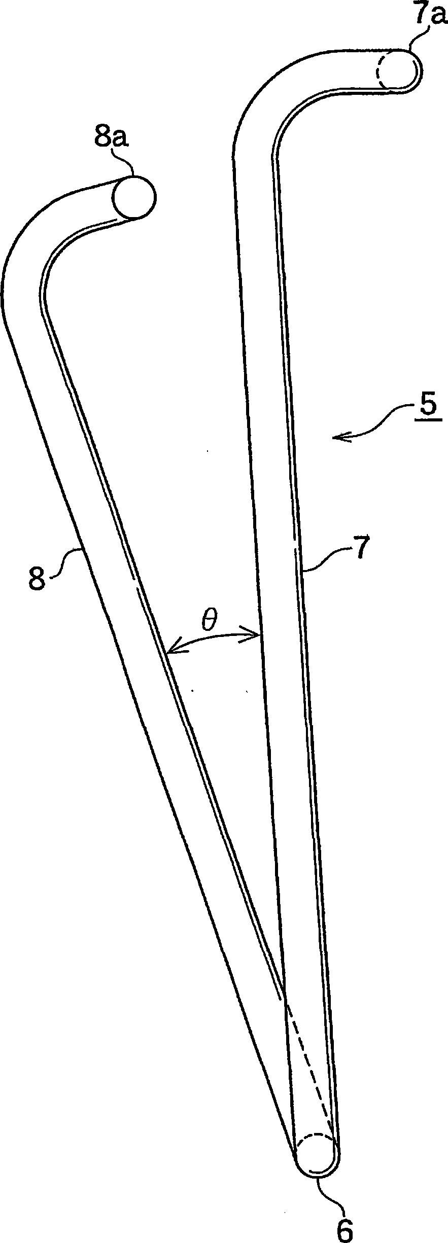
[0049] figure 1 It is a front view of a ballpoint pen equipped with a writing implement clip according to an embodiment of the present invention; figure 2 is a side view of the above-mentioned ballpoint pen; image 3 It is an enlarged side view showing the body of the clip; Figure 4 is an enlarged perspective view of the pen chuck; Figure 5 It is a side view showing the mounting state of the pen clip to the clip body; Figure 6 is a stereogram of the above state; Figure 7 It is a side view showing the attachment state of the above-mentioned pen clip to the ballpoint pen.

[0050] In addition, in the embodiments of the present invention, a ballpoint pen is used as an example of a writing instrument for description, but the present invention is not limited thereto.

[0051] Such as figure 1 and figure 2 As shown, the ballpoint pen 1 is provided with...


PUM


Abstract

This invention provides a pen clip, in which a pen clip head can be easily mounted, the mounting state is excellent and the mounting can be steadily performed corresponding to the writing tool through mounting the pen chip head at the writing tool when the functionality and shape are improved. The pen clip comprises a base body capable mounting the pen clip head between left and right wires at the lower end base part side of the pen clip body when the pen clip head is mounted at the low end base part of the pen clip body which is roughly U-shaped when viewed in a positive position; a first keeping part for rotatably keeping a wire shaft of the lower end base part of the base body which can surround the pen clip body when the lower end part of the base body is formed; a second keeping part that is formed in at least one of left and right sides of the base body and kept on at leas one of left and right wires of the pen clip body, and used for restraining the rotation of the wire shaft of the base body surrounding the lower end base part.

Description

technical field [0001] The present invention relates to a clip for writing implements mounted on writing implements such as ballpoint pens, and more particularly to a clip for writing implements with a feature in the mounting structure of the clip body to the clip body formed by bending metal elastic wires. Background technique [0002] Pen clips installed on writing instruments are known in which the clip body is continuous from the lower end base through a metal elastic wire, and the left and right wires are bent upward to form a substantially U-shaped pen clip when viewed from the front (refer to Patent Documents 1 and 2). [0003] When this pen clip is detachably installed on the mounting part provided on the upper end of the writing instrument body, the upper ends of the left and right wires of the pen clip body are fixed so that the left and right wires are located on approximately the same plane with each other, and at the same time, in order to make the lower end base...

Claims


Application Information

Patent Timeline
IPC IPC(8): B43K25/02
Inventor 谷口俊一
Owner TOMBOW PENCIL CO LTD
Why Eureka
Try Eureka