Pll circuit
A circuit and charge pump technology, applied in the direction of electrical components, automatic power control, etc., can solve the problem of not being able to control the output frequency at a certain value, leakage current, etc., and achieve the effect of good linearity and suppression of time changes.
- Summary
- Abstract
- Description
- Claims
- Application Information
AI Technical Summary
Problems solved by technology
Method used
Image

Examples
Embodiment approach 1
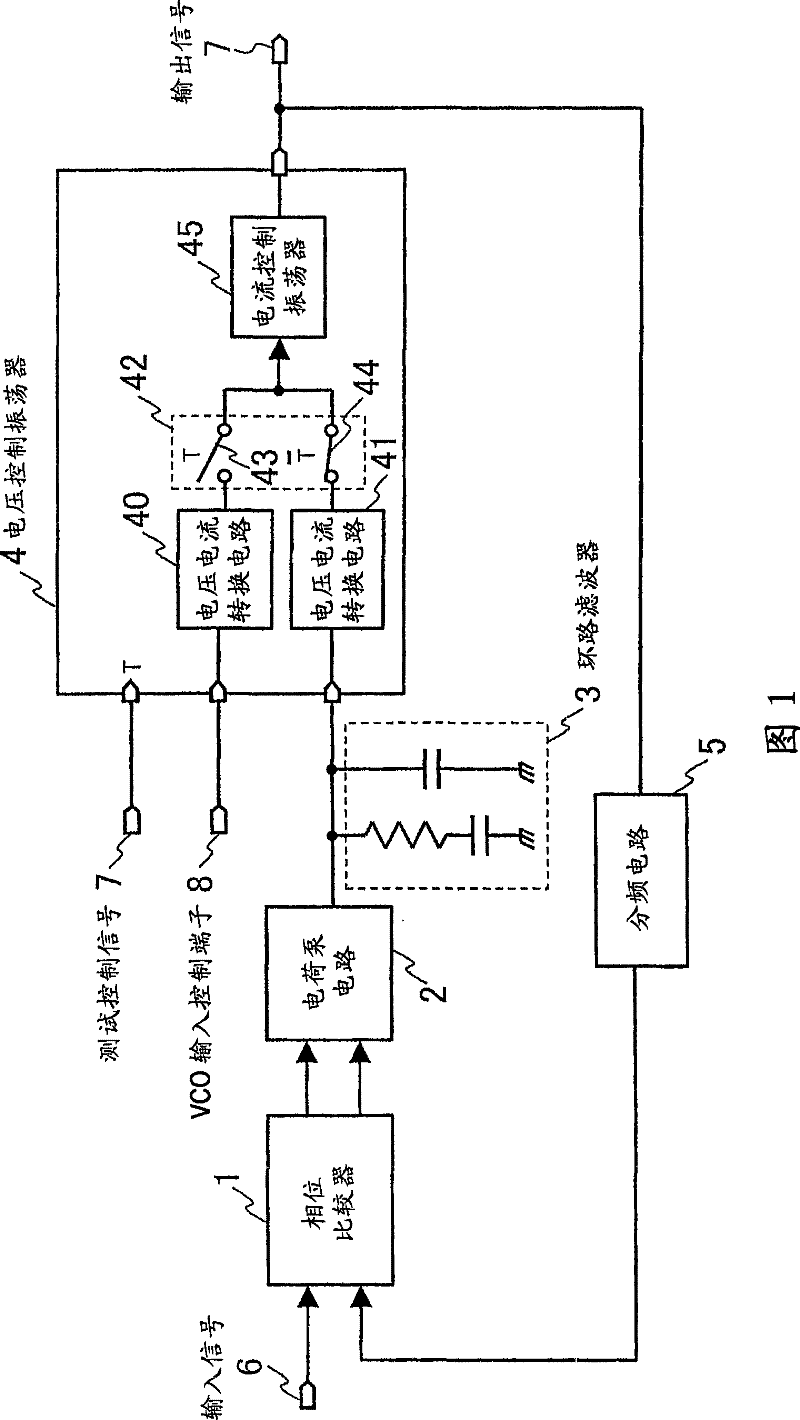
[0059] figure 1 It is a configuration diagram of a PLL circuit according to Embodiment 1 of the present invention.
[0060] exist figure 1 Among them, the PLL circuit is a phase comparator 1 that will detect the phase difference between the input signal 6 and the signal after the output frequency division of the VCO4 in the frequency division circuit 5, and provides the loop filter 3 with the phase difference obtained by the phase comparator 1. The charge pump circuit 2 for the charge corresponding to the detected phase difference signal, the loop filter 3 for smoothing the output signal of the charge pump circuit 2, the VCO4 for controlling the oscillation frequency by using the voltage of the loop filter 3, and the VCO4 for VCO4 The frequency dividing circuit 5 for dividing the output frequency is formed by connecting in a ring. Here, the VCO4 has two input terminals, two voltage-current conversion circuits 40 and 41 that convert the respective voltages of the two input ...
Embodiment approach 2
[0071] Hereinafter, a PLL circuit according to Embodiment 2 of the present invention will be described with reference to the drawings.
[0072] Figure 4 It is a configuration diagram of a PLL circuit according to Embodiment 2 of the present invention.
[0073] exist Figure 4 Herein, parts having the same structure as that of Embodiment 1 are denoted by the same reference numerals, and description thereof will be omitted.
[0074] exist Figure 4 Among them, the difference from Embodiment 1 is that the voltage-current conversion circuits 40 and 41 are composed of an operational amplifier 52 that uses the input terminal of the voltage-current conversion circuit as an input signal on the negative side, and the gate terminal is connected to the output of the operational amplifier 52. , the PTr54 connecting the source terminal to the power supply, the drain terminal to the positive input terminal of the above-mentioned operational amplifier 52, the resistor 53 connected betwee...
Embodiment approach 3
[0077] Hereinafter, a PLL circuit according to Embodiment 3 of the present invention will be described with reference to the drawings.
[0078] Figure 5It is a configuration diagram of a PLL circuit according to Embodiment 3 of the present invention.
[0079] exist Figure 5 In , parts having the same configuration as those in Embodiment 2 are denoted by the same reference numerals, and descriptions thereof are omitted.
[0080] exist Figure 5 In the present invention, the difference from Embodiment 2 is that the input signal on the positive side of the operational amplifier 52 constituting the voltage-current conversion circuit 41, which receives the voltage of the loop filter 3 as an input, is used as a signal for monitoring the loop filter 3. Loop filter voltage monitor terminal 56 for voltage.
[0081] With the configuration as described above, it is possible to observe the potential of the loop filter during PLL operation without adding a new circuit.
PUM
 Abstract
Description
Claims
Application Information
 - R&D
- Intellectual Property
- Life Sciences
- Materials
- Tech Scout
- Unparalleled Data Quality
- Higher Quality Content
- 60% Fewer Hallucinations
Browse by: Latest US Patents, China's latest patents, Technical Efficacy Thesaurus, Application Domain, Technology Topic, Popular Technical Reports.
© 2025 PatSnap. All rights reserved.Legal|Privacy policy|Modern Slavery Act Transparency Statement|Sitemap|About US| Contact US: help@patsnap.com