
Involute arc spout fire-fighting extinguishing spray-head

An involute shape and involute technology, applied in the field of fire extinguishing equipment, can solve the problems of delaying fire extinguishing time, consumption of fire extinguishing agent, etc.

Inactive Publication Date: 2009-02-04
UNIV OF SCI & TECH OF CHINA
View PDF0 Cites 22 Cited by
  • Summary
  • Abstract
  • Description
  • Claims
  • Application Information

AI Technical Summary

Problems solved by technology

[0003] In order to solve the problem of consuming fire extinguishing agent and delaying the fire extinguishing time of the existing circular spout groove sprinkler head, the present invention provides a fire extinguishing sprinkler head with involute arc spout

Method used


Image

  • Involute arc spout fire-fighting extinguishing spray-head
  • Involute arc spout fire-fighting extinguishing spray-head

Examples


Embodiment 1

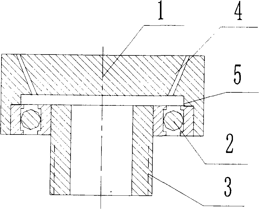
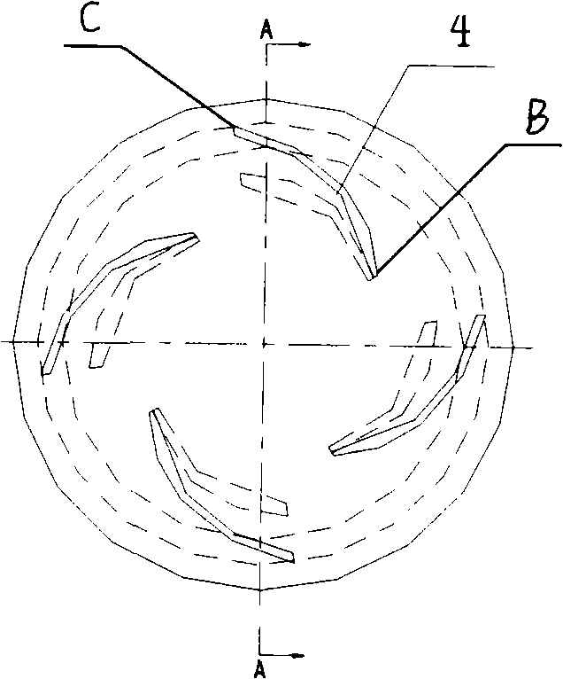
[0014] see figure 1 and figure 2 , a fire extinguishing sprinkler head with an involute arc-shaped nozzle includes a sprinkler head body 1, a bearing 2 and a connecting pipe 3. The sprinkler head body 1 is a cylinder with a diameter of 100mm and a thickness of 13mm. The cylindrical body of the concave step 5, the inner concave step end is connected to the connecting pipe 3 through the bearing 2; the other end is evenly distributed with four spout grooves, the spout grooves are involute in the radial direction, and the center of the circle is the origin of the involute; the involute The line equation is: x=r(cost+tsint), y=r(sint-tcost), where r is the radius of the base circle, with a value of 14mm, t is the spread angle, and its unit is radian, and the value of t is 90°~ 170°, 90° are the starting end B end of the involute spout groove 4, 170° are the end end C end of the involute spout groove 4, the inlet below the spout groove 4 and the outlet above form a certain spray a...

Embodiment 2

[0018] The diameter of the sprinkler head body is 90mm, and the thickness is 10mm; there are two nozzle slots evenly distributed on the sprinkler head body. The slot width is 0.5; the jet angle at the terminal end C of the involute spout slot is 40 degrees, where the slot width at the entrance of the spout slot is 0.7 mm, and the slot width at the exit is 0.6 mm; the radius r of the involute base circle is 10 mm.

[0019] Others are with embodiment 1.

Embodiment 3

[0021] The diameter of the sprinkler head body is 120mm, and the thickness is 15mm; there are three nozzle slots evenly distributed on the sprinkler head body, and the spray angle at the beginning end B of the involute nozzle slot is 80 degrees. The groove width of the involute spout groove is 2.8mm; the injection angle at the end C of the involute spout groove is 40 degrees, where the groove width of the nozzle groove inlet is 2.6mm, and the groove width of the outlet is 2.5mm; the radius r of the involute base circle is 16mm .

[0022] Others are with embodiment 1.


PUM


Abstract

The invention relates to an involute arc spout fire extinguishing sprinkler head of a fire extinguishing device with a mechanical liquid sprinkling fire extinguishing agent, which solves the problem that the existing circular spout groove sprinkler head costs fire extinguishing agent and delays fire extinguishing time. The sprinkler head comprises a sprinkler head body, a bearing and a connecting pipe; the spout groove is involute arc along the radial direction; the spraying angle of B end which is the starting end of the involute arc spout groove 4 is 70-85 degrees, the spraying angle of C end which is the ending end of the involute arc spout groove 4 is 40-45 degrees, and the base radius r of the involute is 10-15mm. The spout groove is in the involute shape, thus the sprayed fire extinguishing agent forms a round cake shape while being sprayed, which is good for fire extinguishing. The sprinkler head is applied to liquid extinguishing agents comprising water, aqueous film forming foam concentrate, and the like. The sprinkler head has the advantages of extinguishing fire in a short time with a few fire extinguishing agents, low fire extinguishing cost, high fire extinguishing efficiency, convenient use, flexible action, saving time and high efficiency, and is applied to oil fire of aerosheds, etc.

Description

technical field [0001] The invention belongs to the technical field of fire extinguishing equipment, and in particular relates to a fire extinguishing spray head of a mechanical fluid spraying fire extinguishing agent fire extinguishing device. Background technique [0002] In order to prevent and extinguish oil fires that leak from the ground or high places and flow to the ground, fire extinguishing sprinklers are arranged on the ground, and the fire extinguishing agent is sprayed from bottom to top, especially in places such as hangars, such sprinklers are often used to spray water or water to form a film Fire extinguishing agent such as foam liquid. Existing fire extinguishing device of this type is to adopt the shower head of ring-shaped spout groove, and the aqueous film-forming fire extinguishing agent sprayed from the ring spout forms a ring shape, and the fire is extinguished by the foam liquid self-diffusion covering the oil surface, which not only wastes the fire e...

Claims


Application Information

Patent Timeline
Patent Type & Authority Applications(China)
IPC IPC(8): A62C31/05
Inventor 秦俊李权威唐海东倪佳迪
Owner UNIV OF SCI & TECH OF CHINA
Learn More