Method for clearly displaying low carbon low alloy steel austenite crystal
A technology for austenite grains and low alloy steels, applied in the metallographic structure display method, can clearly display the field of austenite grains of low carbon steel and low alloy steel, and can solve the problem that the austenite grain boundary cannot be displayed and the austenite grain boundary is difficult Display, unable to display austenite grain boundaries and other problems, to achieve the effect of ensuring product quality and reasonable control of process parameters
- Summary
- Abstract
- Description
- Claims
- Application Information
AI Technical Summary
Problems solved by technology
Method used
Image
Examples
Embodiment 1
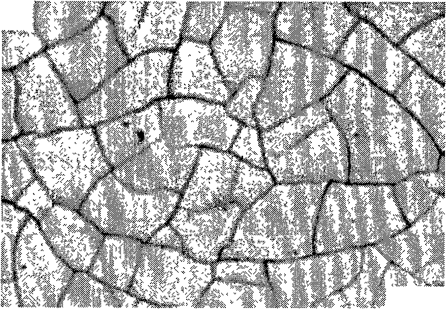
[0016] Example 1: The chemical composition of sample 1 is C: 0.08%, Si: 0.24%, Mn: 1.36%, V: 0.035%, Ti: 0.023%, Nb: 0.030%, Als: 0.032%, P: 0.012% , S: 0.003%. Sample quenching: heat the sample to 1050°C, keep it warm for a certain period of time, let the carbides dissolve in the matrix, and then quench the sample in water with a temperature lower than 20°C; grind and polish the quenched sample; The following ratio is used to configure the etchant: CrO 3 9g, NaOH 40g, picric acid 1.6g, ethylene oxide 2ml, distilled water 80ml. When preparing, first measure 80ml of distilled water and put it in a container, then add CrO to the distilled water 3 , to be CrO 3 Add NaOH after complete dissolution. Since the amount of NaOH is large and it will produce a strong exothermic reaction, it should be added slowly to avoid splashing. After adding NaOH, add picric acid solution and ethylene oxide. The prepared etchant solution was heated to 110°C and kept warm on a constant temperatu...
Embodiment 2
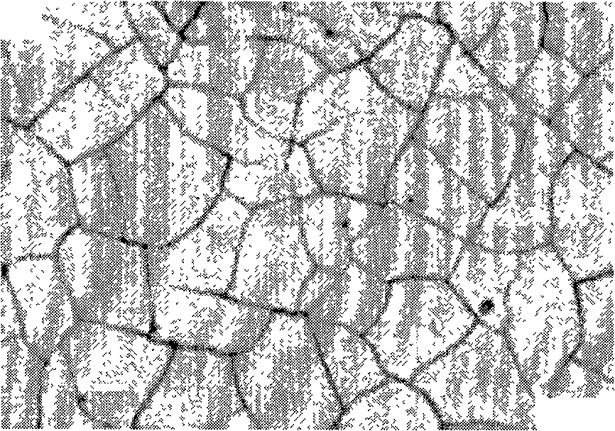
[0017] Example 2: The chemical composition of sample 2 is C: 0.05%, Si: 0.20%, Mn: 1.45%, Mo: 0.17%, Ti: 0.017%, Nb: 0.042%, Als: 0.030%, P: 0.010% , S: 0.005%. Sample quenching: heat the sample to 1150°C, keep it warm for a certain period of time, let the carbides dissolve in the matrix, and then quench the sample in water with a temperature lower than 20°C; grind and polish the quenched sample; The following ratio is used to configure the etchant: CrO 3 10g, NaOH 50g, picric acid 1.8g, ethylene oxide 3ml, distilled water 90ml. Preparation method is with embodiment 1. Heat the prepared etchant solution to 120°C and keep it warm on a constant temperature heating furnace, then put the polished sample into the solution for etching, with the etched side of the sample facing up, and the etching time is 50 minutes. When the polished surface of the sample turns iron blue, take it out, wash it and dry it, and then observe the austenite grains under the microscope. Depend on fi...
Embodiment 3
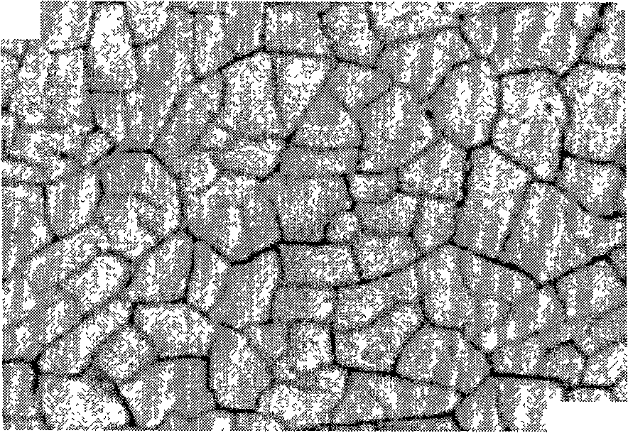
[0018] Example 3: The chemical composition of sample 3 is C: 0.03%, Si: 0.20%, Mn: 1.72%, Mo: 0.25%, Ti: 0.015%, Nb: 0.040%, V: 0.050%, Cu: 0.2% , Als: 0.025%, P: 0.014%, S: 0.004%. Sample quenching: heat the sample to 1200°C, keep it warm for a certain period of time, let the carbides dissolve in the matrix, and then quench the sample in water with a temperature lower than 20°C; grind and polish the quenched sample; The following ratio is used to configure the etchant: CrO 3 8g, NaOH 45g, picric acid 2g, ethylene oxide 4ml, distilled water 100ml. Preparation method is with embodiment 1. Heat the prepared solution to 130°C and keep it warm on a constant temperature heating furnace, then put the polished sample into the solution for etching, with the etched side of the sample facing up, and the etching time is about 60 minutes. When the polished surface of the sample turns iron blue, take it out, wash it and dry it, and then observe the austenite grains under the microscope...
PUM
 Abstract
Description
Claims
Application Information
 - R&D
- Intellectual Property
- Life Sciences
- Materials
- Tech Scout
- Unparalleled Data Quality
- Higher Quality Content
- 60% Fewer Hallucinations
Browse by: Latest US Patents, China's latest patents, Technical Efficacy Thesaurus, Application Domain, Technology Topic, Popular Technical Reports.
© 2025 PatSnap. All rights reserved.Legal|Privacy policy|Modern Slavery Act Transparency Statement|Sitemap|About US| Contact US: help@patsnap.com


