Turbomachine rotor assembly

A turbine and rotor technology, applied to engine components, pump components, mechanical equipment, etc., can solve problems that affect the service life of turbines and support surface wear

Active Publication Date: 2009-01-14
SN DETUDE & DE CONSTR DE MOTEURS DAVIATION S N E C M A
View PDF1 Cites 10 Cited by
  • Summary
  • Abstract
  • Description
  • Claims
  • Application Information

AI Technical Summary

Problems solved by technology

In addition, for the dynamic motion of the blade at a given rotational speed, the reaction of the blade to resonant or momentary alternating stresses can also cause the phenomenon of wear on the support surface
These wear phenomena will undoubtedly affect the service life of the turbine

Method used


Image

  • Turbomachine rotor assembly
  • Turbomachine rotor assembly
  • Turbomachine rotor assembly

Examples


Embodiment Construction

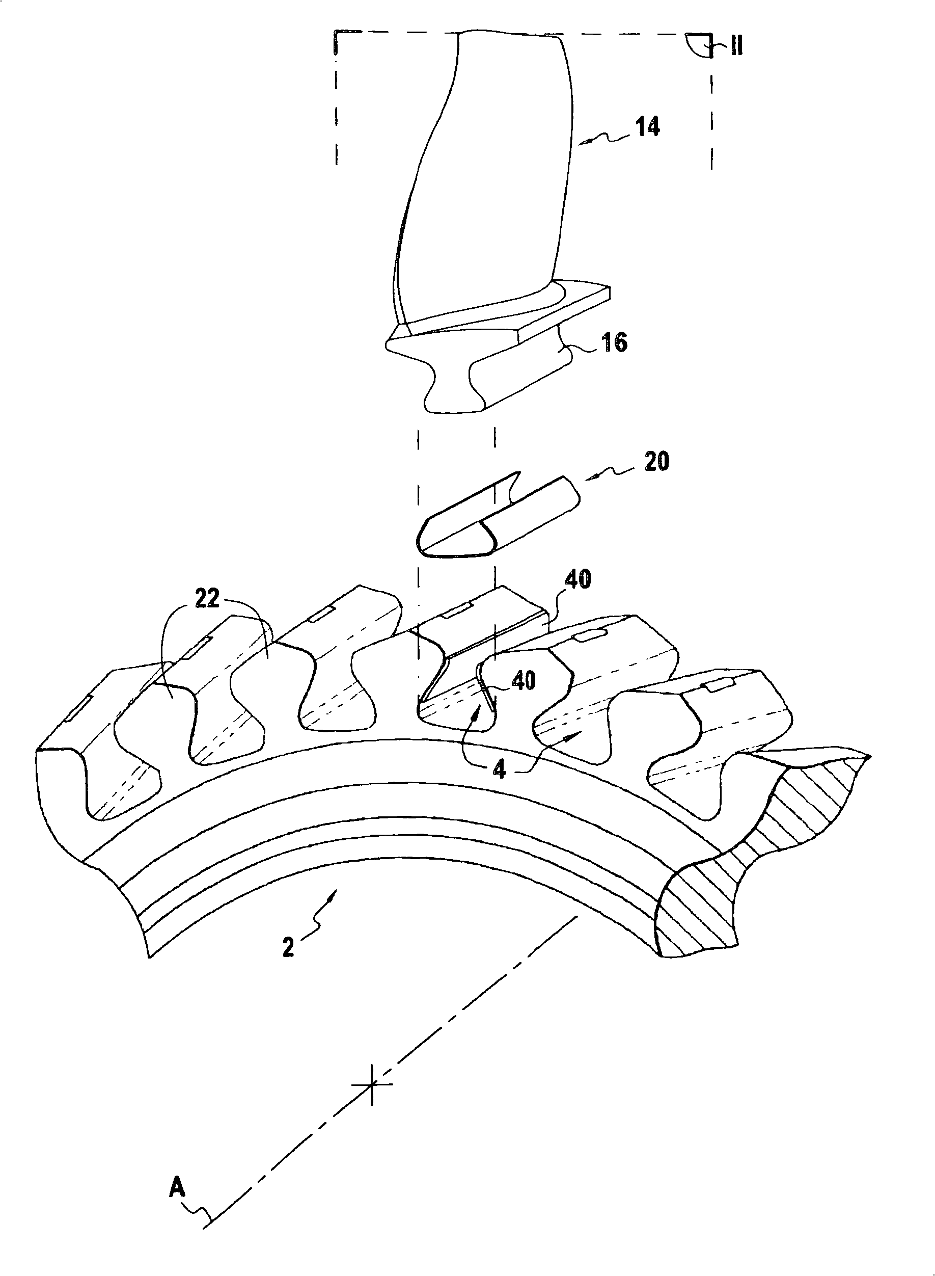
[0026] Such as figure 1 and figure 2 As shown, the rotor disk 2 is provided with a number of grooves or "slots" 4 along its outer edge, which form cavities, each of which can receive a blade root 16 of a blade 14, around which the blade root 16 is lined. Pad 20. The blade root 16 and the fan disk 2 are made of, for example, a titanium alloy.

[0027] It should be noted that these assemblies are also provided with a spacer (not shown) between the blade root 16 and the bottom of the slot 4 .

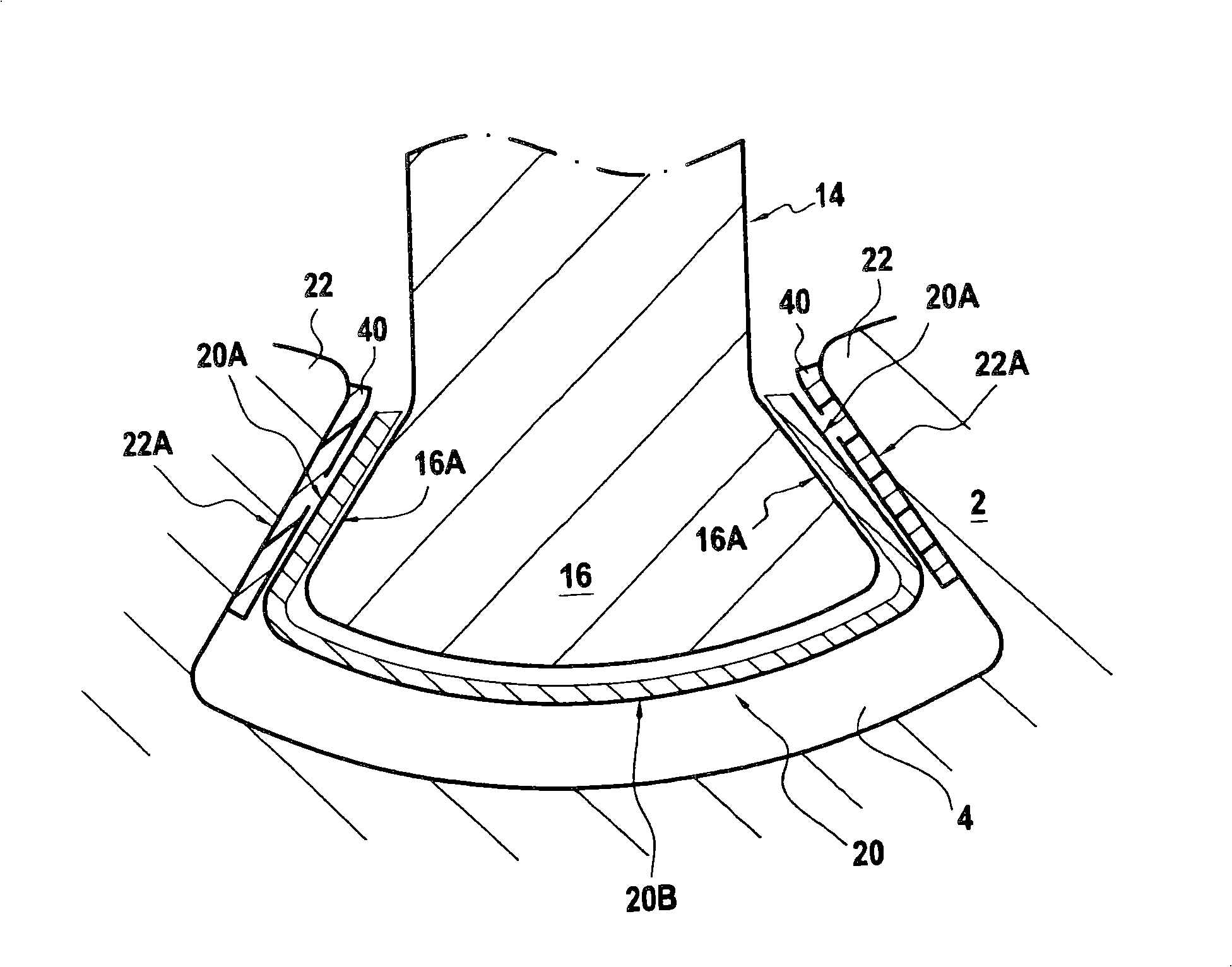
[0028] When the wheel disk 2 rotates, the blade 14 bears the centrifugal force, and the support surface 16A on the blade root 16 will be tightly pressed on the support surface 22A of the wheel disk 2 . In the example described, the support surfaces 16A form the wings of the blade root 16 , while the support surfaces 22A form the underside of the wheel lip 22 extending on both sides of the outer opening of each slot 4 .

[0029] The liner 20 includes two side walls 20A intended to come...


PUM


Abstract

A turbomachine rotor assembly comprising: a rotor disk (2) presenting slots (4) in its outer periphery; blades (14) fastened via their roots (16) in said slot (4); and shims (20) mounted between the blade roots (16) and the disk (2), each shim (20) comprising two branches (20A) and a base part (20B) interconnecting the branches, each branch (20A) being disposed between the bearing surface (16A) of a blade root (16) and the corresponding bearing surface (22A) of the disk (2); each branch (20A) being made of a first material presenting a first Young's modulus of value E, at any operating temperature in the operating temperature range of the shim (20). The rotor assembly includes pads (40) adhering to the bearing surfaces (22A) of the disk and / or to the bearing surfaces (16A) of the blade root, the pads (40) being made of a second material presenting a second Young's modulus of value lying in the range E / 20 to E / 5 at said operating temperature.

Description

technical field [0001] The invention relates to a turbine rotor assembly. Background technique [0002] When the rotor rotates, the blade mainly bears the centrifugal force and also bears the axial aerodynamic force, while the blade root is butted and pressed with the wheel discs located on both sides of the outer opening of each slot under the action of the centrifugal force. The surface where the blade root and the disc abut against each other is often referred to as the "support surface". These support surfaces are under pressure due to said centrifugal and aerodynamic forces acting on said support surfaces. According to a first approximation, it is estimated that this pressure depends on the square of the rotational speed of the rotor. [0003] Thus, one would know the change in the rotational speed of the rotor during the working cycle of the turbine: from standstill to full throttle, through various intermediate speeds, which in the case of aviation turbines means id...

Claims


Application Information

Patent Timeline
Patent Type & Authority Applications(China)
IPC IPC(8): F01D5/02F01D5/30F01D5/28F04D29/34
CPCF04D29/322Y02T50/672F01D5/3007Y02T50/673F01D5/3092Y02T50/60
Inventor 查尔斯·杜盖克里斯托弗·雅克让-皮埃尔·隆巴德
Owner SN DETUDE & DE CONSTR DE MOTEURS DAVIATION S N E C M A
Why Eureka
Try Eureka