
Dual-speed self-tapping machine tool

An automatic tapping and machine tool technology, applied in the field of machine tools, can solve the problems of reducing work efficiency, unbalanced force on the power head, easy to attack deviation, etc., and achieve the effect of reducing labor intensity, improving work efficiency and reasonable structure

Inactive Publication Date: 2009-01-14
浙江速成精密机械有限公司
View PDF0 Cites 9 Cited by
  • Summary
  • Abstract
  • Description
  • Claims
  • Application Information

AI Technical Summary

Problems solved by technology

[0002] Because the manual tapping machine tool is cheap, it is still widely used at present. The movement of the power head of the manual tapping machine includes rotary motion and up and down motion. The dynamic gear transmission mechanism converts the rotational motion of the gear into the up and down reciprocating motion of the power head (the power head is equipped with a tool), but it has the following disadvantages: First, when it is turned by hand, the force is often biased to one side, causing the power head to be stressed. Unbalanced, especially when tapping deep threads, it is easy to deviate, poor concentricity, and difficult to guarantee product quality; second, the power head only advances at the same low speed no matter it is empty or loaded, and this low speed That is to ensure the normal tapping speed, but there is no load when the tool is fed before tapping and retracted after tapping. If the working speed is still used, the work efficiency will be greatly reduced; third, manual operation is labor-intensive.

Method used


Image

  • Dual-speed self-tapping machine tool
  • Dual-speed self-tapping machine tool
  • Dual-speed self-tapping machine tool

Examples


Embodiment Construction

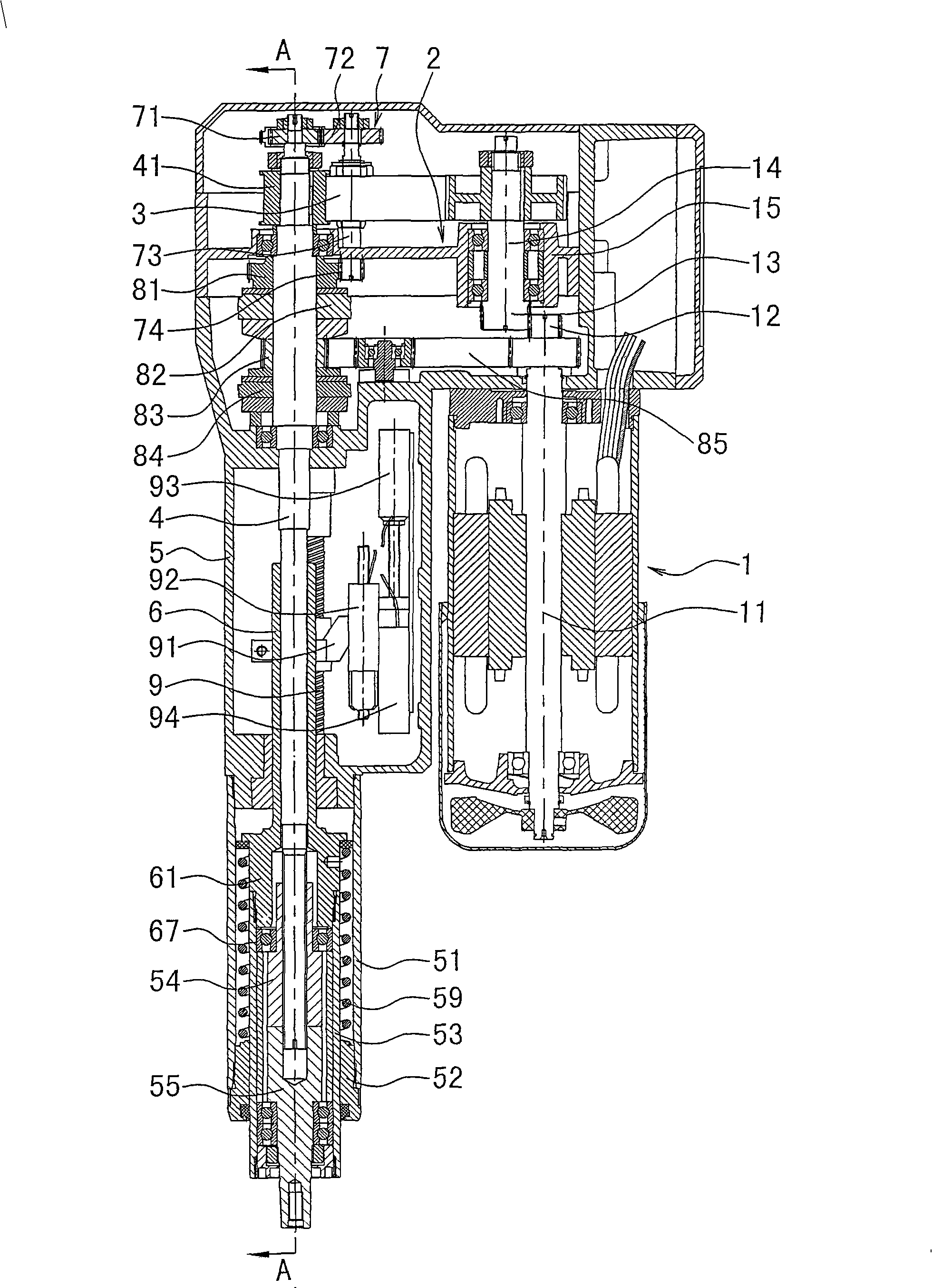
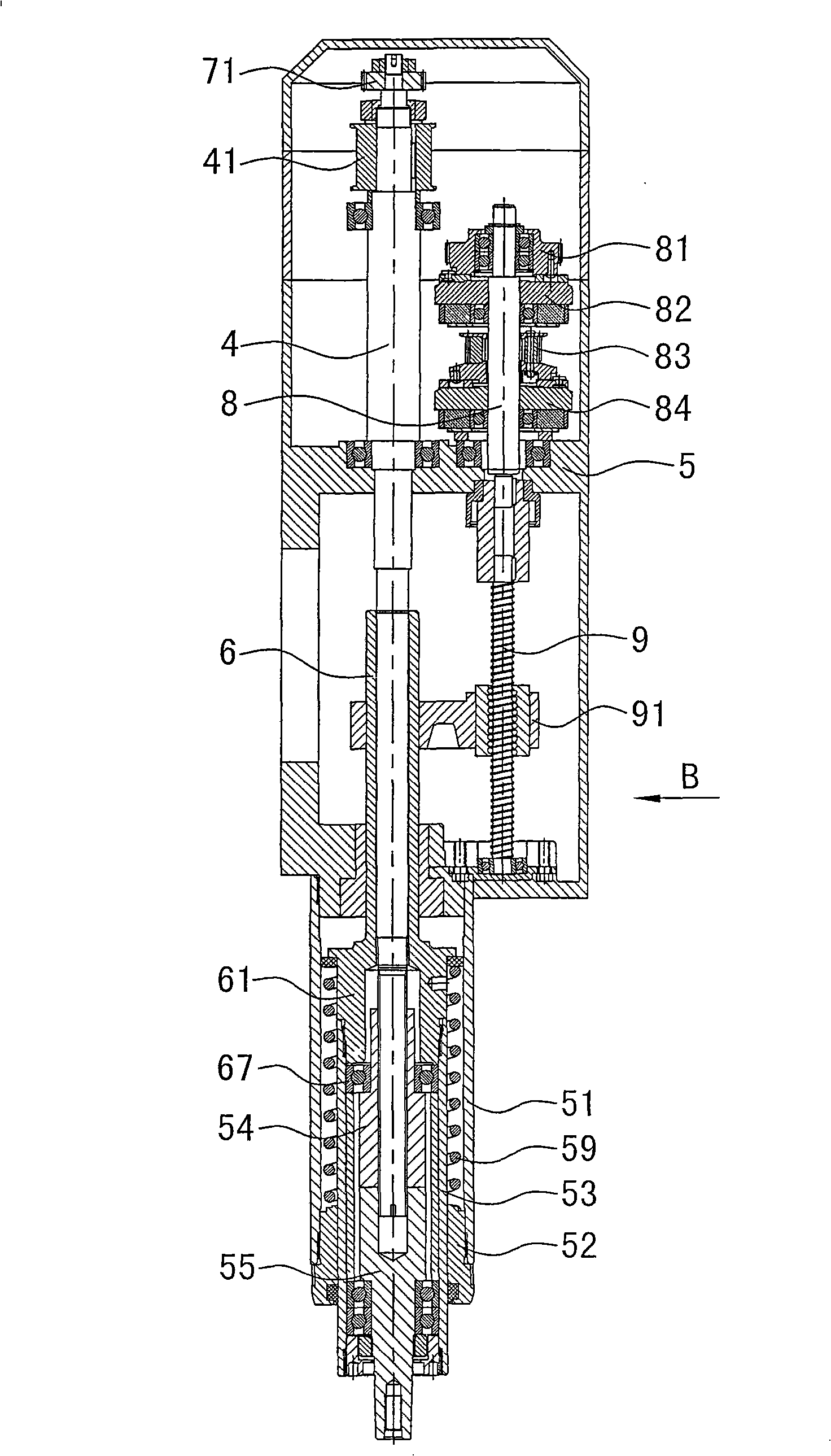
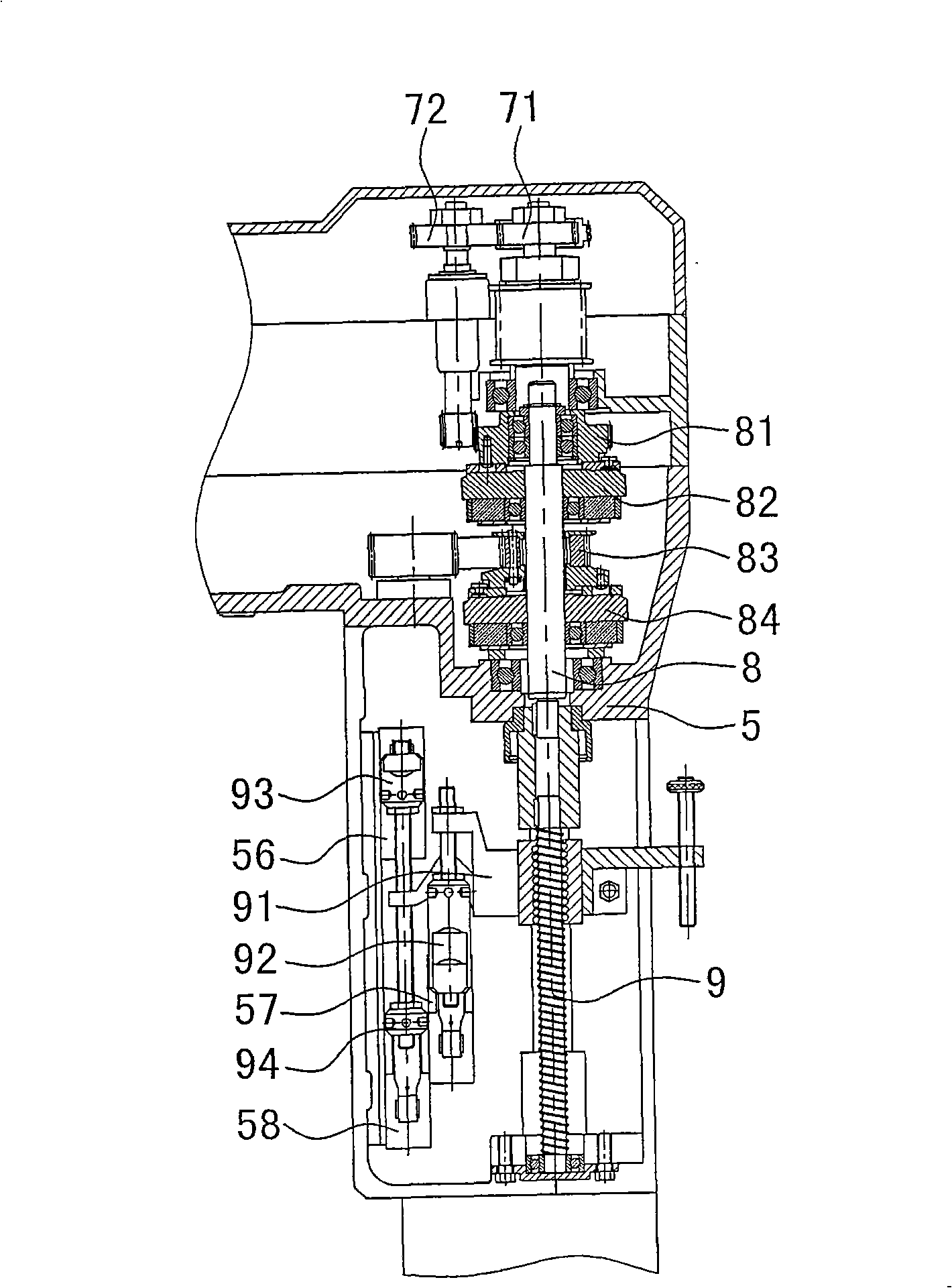
[0010] The invention discloses a two-speed automatic tapping machine tool, such as Figure 1-Figure 3 As shown, it includes the motor shaft 11 driven by the motor 1, the motor shaft is connected to the deceleration mechanism 2, the deceleration mechanism is meshed with the slow synchronous wheel 41 through the slow transmission belt 3, and the slow synchronous wheel 41 is fixed outside the spline shaft 4. The key shaft 4 is installed in the box body 5, and the middle and lower part of the spline shaft is movable to install the piston rod 6. The piston rod 6 is provided with a piston 61, and the bottom head of the spline shaft is screw connected with the power head. Connected outer cylinder 51, the outer cylinder is equipped with a lower end cover 52, a piston cylinder 53 is housed in the lower end cover, a spring 59 is housed between the piston cylinder 53 and the outer cylinder 51, and the top of the piston cylinder is in contact with the piston 61. Contact, the main shaft up...


PUM


Abstract

The invention discloses a double-speed automatic tapping machine, comprising a motor shaft driven by a motor. The motor shaft is connected with a decelerating mechanism which connects with a spline shaft via a transmission belt of slow speed. The spline shaft is positioned in the box, the central and lower part outside of the spline shaft is movably provided with a piston rod. The lower end of the piston rod is provided with a piston. The lower end of the spline shaft is spirally connected with a power head. The upper end of the power head is connected with the piston via a bearing, and the lower end of the power head is connected with a cutting tool. The invention is characterized in that: the spline shaft is connected with an accessory shaft via an intermediate transmission mechanism. A clutch gear, a clutch of slow speed, a fast synchronizing wheel and a clutch of fast speed are positioned at outside of the accessory shaft from top to bottom. The clutch gear is tightly fixed with the clutch of slow speed. The fast synchronizing wheel is tightly fixed with the clutch of fast speed. The fast synchronizing wheel is directly connected with the motor shaft via the transmission belt of fast speed. The lower end of the accessory shaft is fixedly connected with a ball screw which is covered with a limit seat. One side of the limit seat is provided with a travel switch, and the other side of the limit seat is fixedly connected with the piston rod.

Description

technical field [0001] The invention relates to a tapping machine, in particular to a two-speed automatic tapping machine tool capable of fast forwarding without load and slow forwarding under load, and belongs to the field of machine tools. Background technique [0002] Because the manual tapping machine tool is cheap, it is still widely used at present. The movement of the power head of the manual tapping machine includes rotary motion and up and down motion. The dynamic gear transmission mechanism converts the rotational motion of the gear into the up and down reciprocating motion of the power head (the power head is equipped with a tool), but it has the following disadvantages: First, when it is turned by hand, the force is often biased to one side, causing the power head to be stressed. Unbalanced, especially when tapping deep threads, it is easy to deviate, poor concentricity, and difficult to guarantee product quality; second, the power head only advances at the same ...

Claims


Application Information

Patent Timeline
IPC IPC(8): B23G1/18B23G1/44B23G11/00
Inventor 应云富
Owner 浙江速成精密机械有限公司
Learn More