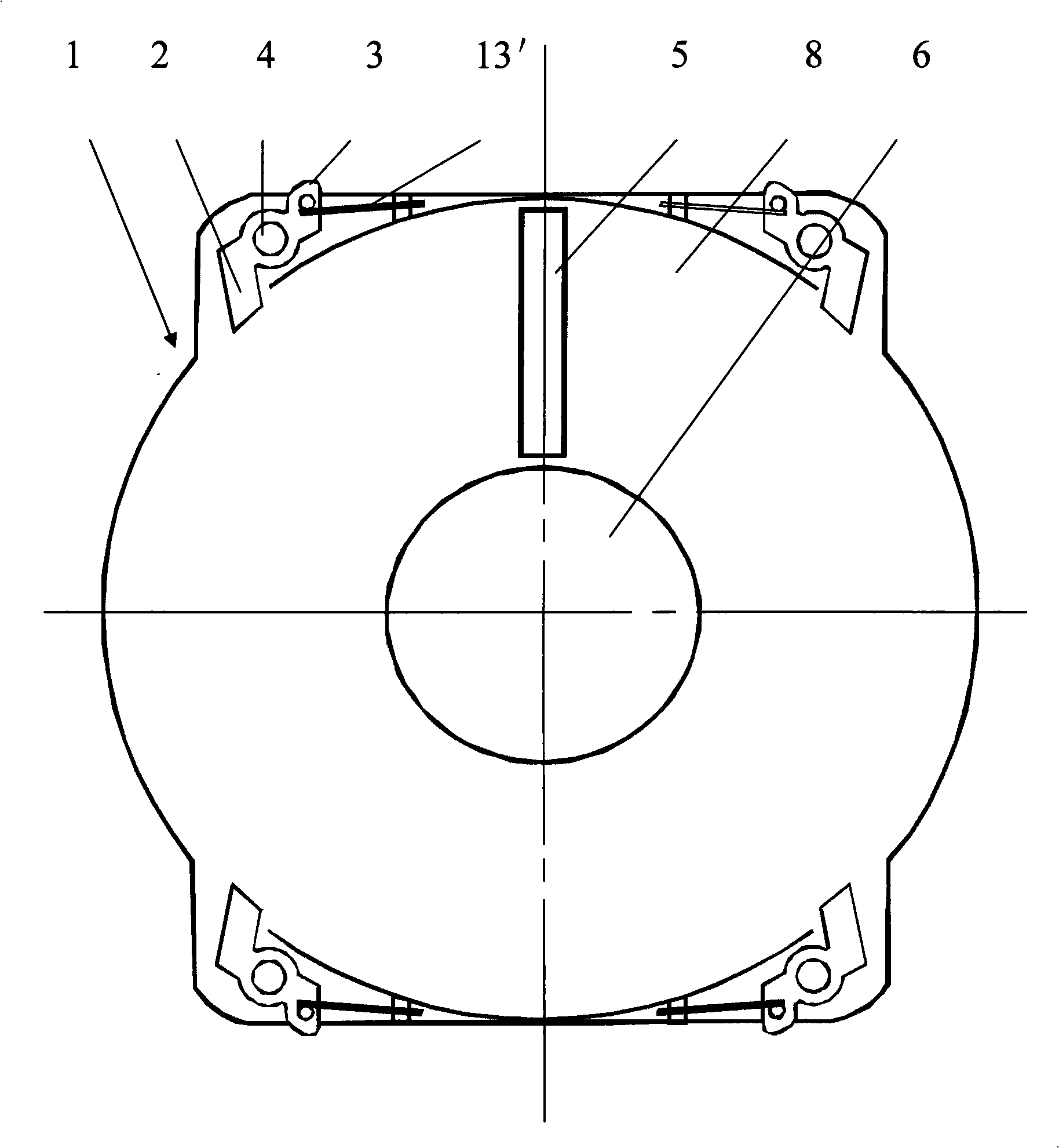
Single side disc protecting box and optical disc read-write apparatus matching therewith
A single-sided technology for reading and writing equipment, applied in the field of mechanical disc fixing mechanism and optical disc reading and writing equipment, it can solve the problems of complex mechanical movement, inability to guarantee the release effect of the optical disc, and increase in cost, so as to achieve a simple structure, a compact disc and other problems. The effect of guaranteeing the effect and saving the manufacturing cost
- Summary
- Abstract
- Description
- Claims
- Application Information
AI Technical Summary
Problems solved by technology
Method used
Image
Examples
Embodiment 1
[0055] Such as figure 1 , 2 shown.
[0056] The single-sided disc guard (1) is provided with a circular disc slot (8), the disc slot (8) can hold a disc (7), and the middle part of the disc slot (8) is provided with a circular top disc hole (6), the diameter of the top disc hole (6) is greater than the diameter of the disk motor head of the optical disc reading and writing equipment, and is less than the diameter of the non-data track area on the inner edge of the optical disc (7). The radius of the optical disc groove (8) The direction face is also provided with 1 optical head reading and writing window (5) equal to the radius of the data track of the optical disc (7), and the width of the optical head reading and writing window (5) can make the optical head of the optical disc reading and writing device pass through this window normally. The data of reading and writing optical disc (7) is advisable; The periphery of optical disc slot (8) is provided with 4 expansion areas,...
Embodiment 2
[0066] Such as Figure 8 , 9 , 10 shown.
[0067] With full reference to the basic design scheme of Embodiment 1, the similarities with Embodiment 1 will not be repeated, and the difference is:
[0068] The automatic extruding device provided on the optical disc bracket (15) of the optical disc reading and writing device (14) is composed of an extruding body (17) respectively arranged in the vertical direction at the left and right ends of the optical disc bracket (15), The middle of the extruding body (17) is straight and long, and its two ends have crotch, so that when extruding the single-sided disc protection case (1), it can directly prevent the single-sided disc protection case (1) from being held by the disc holder. The horizontal plane direction of frame (15) slips off.
[0069] Each extruding body (17) is provided with a rotating mechanism (4) near the lower end of the disc tray (15), and the extruding body (17) realizes movement through the rotating mechanism (4) ...
Embodiment 3
[0073] Such as image 3 , 11 , 12 shown.
[0074] With full reference to the basic design scheme of Embodiment 1, the similarities with Embodiment 1 will not be repeated, and the difference is:
[0075] The specific length of the power body (3) set in the single-sided disc protection box (1) does not exceed the outermost edge of the single-sided disc protection box (1), and the corresponding single-sided disc protection box (1) of each power body (3) There is also a squeezing groove (10) on the position, and the squeezing groove (10) forms an opening structure on the outermost edge of the single-sided disc guard box (1), and one end of the power body (3) is built into the In the extrusion groove (10), the single-sided disc protection case (1) is exposed by the extrusion groove (10).
[0076] The spring limit mechanism set on the single-sided disc protection box (1) also includes 4 limit heads (9), and the limit heads (9) are formed by the upward protrusions on the surface o...
PUM
 Abstract
Description
Claims
Application Information
 - Generate Ideas
- Intellectual Property
- Life Sciences
- Materials
- Tech Scout
- Unparalleled Data Quality
- Higher Quality Content
- 60% Fewer Hallucinations
Browse by: Latest US Patents, China's latest patents, Technical Efficacy Thesaurus, Application Domain, Technology Topic, Popular Technical Reports.
© 2025 PatSnap. All rights reserved.Legal|Privacy policy|Modern Slavery Act Transparency Statement|Sitemap|About US| Contact US: help@patsnap.com


