
Method and apparatus implementing broadcast channel covering by antenna array

An antenna array and broadcast channel technology, which is applied in the direction of selection device, diversity/multi-antenna system, transmission control/equalization, etc., can solve the problems of array antenna broadcast channel coverage, etc.

Inactive Publication Date: 2008-12-31
JIANGSU HUACAN TELECOMM
View PDF1 Cites 10 Cited by
  • Summary
  • Abstract
  • Description
  • Claims
  • Application Information

AI Technical Summary

Problems solved by technology

[0007] The technical problem to be solved by the present invention is to provide a method and device for realizing broadcast channel coverage by an antenna array, and solve the problem of how to realize broadcast channel coverage by an array antenna

Method used


Image

  • Method and apparatus implementing broadcast channel covering by antenna array
  • Method and apparatus implementing broadcast channel covering by antenna array
  • Method and apparatus implementing broadcast channel covering by antenna array

Examples


Embodiment Construction

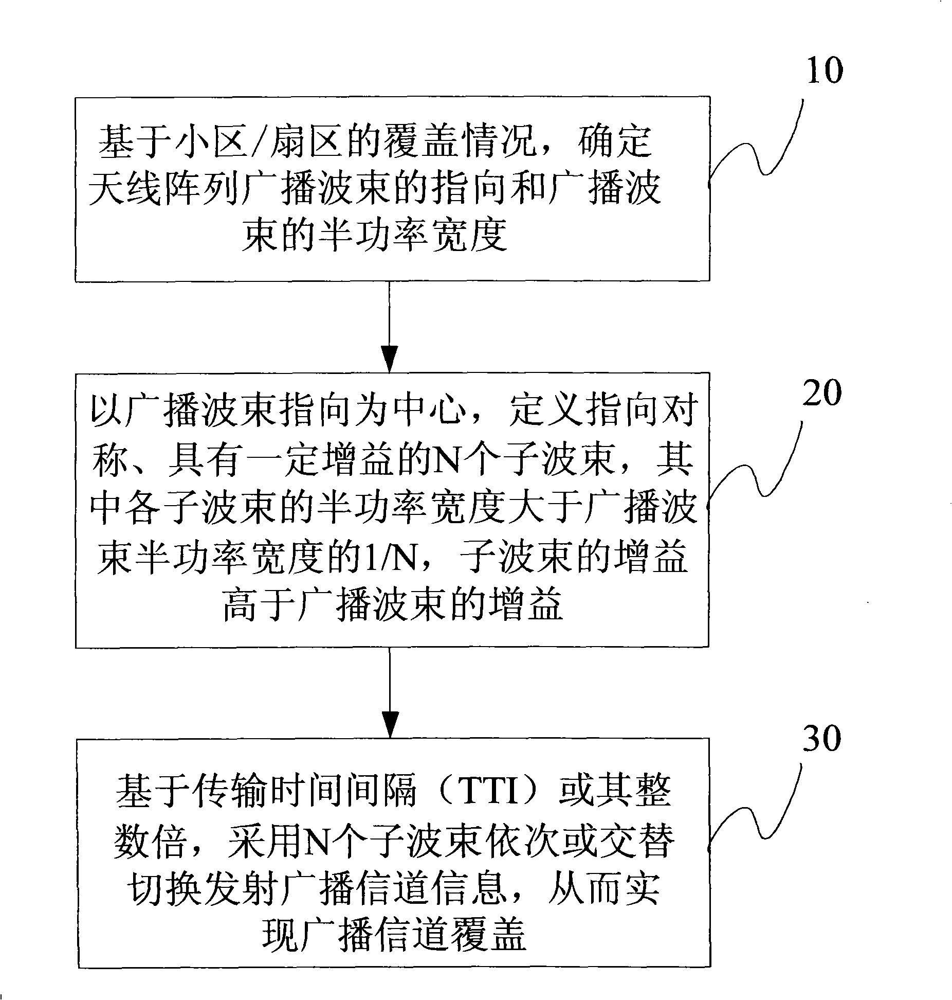
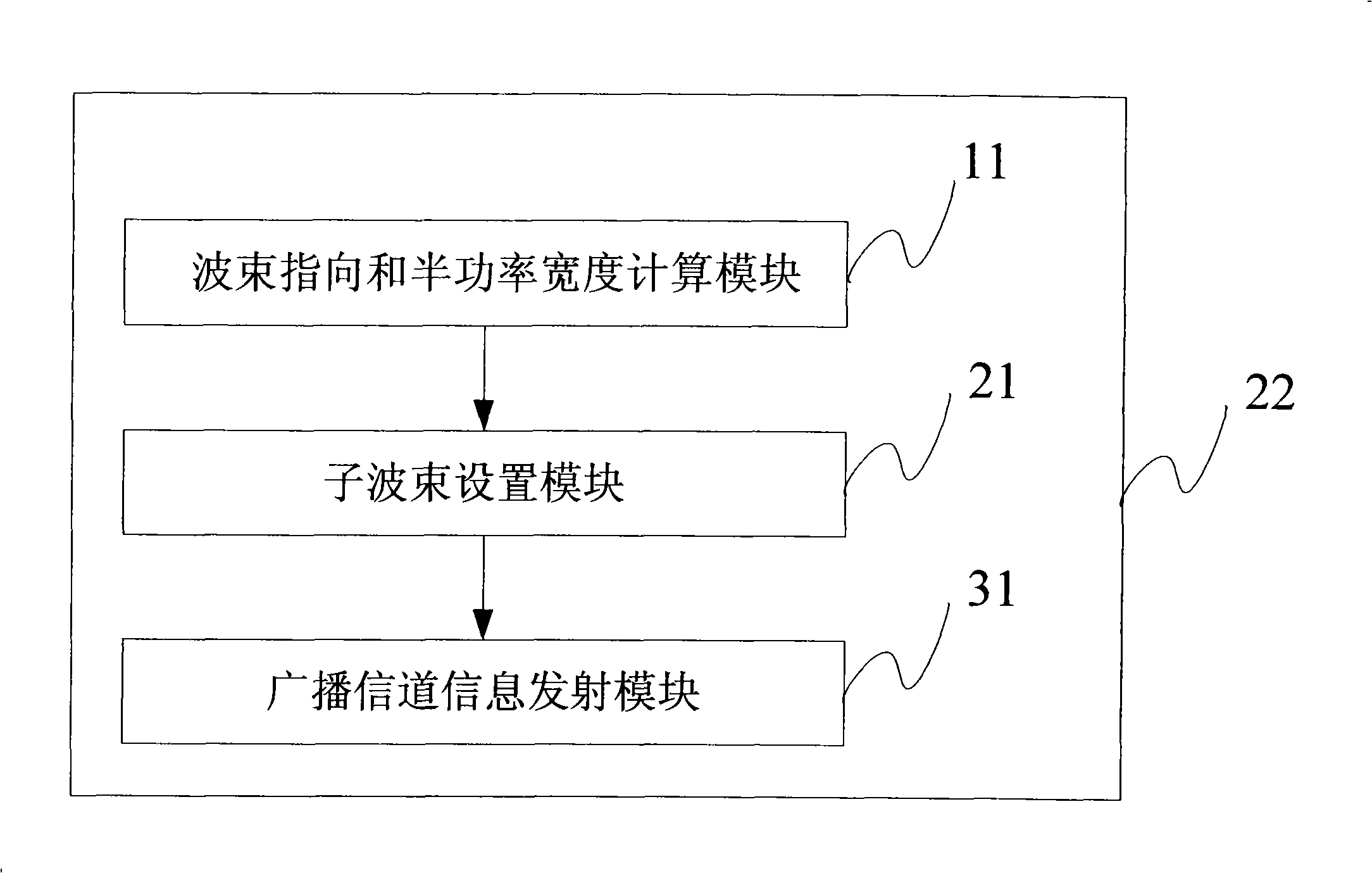
[0035] The present invention provides a method for implementing antenna array broadcast channel coverage, that is, by setting multiple sub-beams, and based on the transmission time interval (TTI) or its integer multiples, using multiple sub-beams to switch sequentially or alternately to transmit broadcast channel information, thereby realizing broadcasting channel coverage.

[0036] A method for implementing antenna array broadcast channel coverage in an embodiment of the present invention is as follows, as follows: figure 1 Shown:

[0037] Step 10, based on the coverage of the cell / sector, determine the direction of the broadcast beam of the antenna array and the half power width of the broadcast beam.

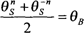
[0038] Among them, the direction of the broadcast beam of the antenna array is θ B , the half-power width (beamwidth) of the broadcast beam is Ω B . The gain of the broadcast beam is denoted as ρ B .

[0039] Step 20, centering on the broadcast beam pointing, set N sub-...


PUM


Abstract

The invention relates to a method for realizing broadcast channel covering by an antenna array, which is used in a smart antenna system, the method includes the following steps that: step 1. according to the coverage condition of communities / sectors, the steering of the antenna array broadcast beam and the half power width of the broadcast beam are calculated; step 2. the broadcast beam steering is takn as a center, N sub-beams (N is a natural number) with symmetric steering are set up according to the calculation results; step 3. on the basis of the interval of transmission time or the integral multiple of the transmission time, broadcasting channel information is emitted by adopting the N sub-beams. The invention can acquire higher beam gain, modify the disequilibrium of the coverage area for broadcast channels and dedicated channels, and promote the network performance of the system.

Description

technical field [0001] The present invention relates to a wireless communication system, in particular to a method and device for implementing broadcast channel coverage by an antenna array. Background technique [0002] The antenna array is mainly used in the smart antenna system. The smart antenna refers to the use of the spatial characteristics of signal transmission and digital signal processing technology to realize spatial filtering and beamforming for the received service signals of dedicated channels, so as to reduce noise interference and increase capacity. , Expand coverage, improve communication quality, reduce transmission power and increase wireless data transmission rate. [0003] For the downlink, the beam gain of the smart antenna includes the power gain and beamforming gain of multiple antennas. Power gain refers to the gain of the sum of the transmit power of all antennas relative to the transmit power of a single antenna. If the transmit power of each ant...

Claims


Application Information

Patent Timeline
Patent Type & Authority Applications(China)
IPC IPC(8): H04B7/04H04B7/005H04Q7/38
Inventor 秦洪峰
Owner JIANGSU HUACAN TELECOMM
Learn More