
Power distributing reactive optimizing compensation system based on GPRS and control method thereof

A control method and compensation system technology, applied in reactive power compensation, reactive power adjustment/elimination/compensation, etc., can solve problems such as high cost, lack of coordination, lack of communication and remote control functions, etc., to prevent voltage drop, Solve the effect of poor anti-interference ability

Inactive Publication Date: 2008-12-31
HUNAN UNIV
View PDF0 Cites 25 Cited by
  • Summary
  • Abstract
  • Description
  • Claims
  • Application Information

AI Technical Summary

Problems solved by technology

But it can only compensate capacitive reactive power, and it is regulated in stages
When the separate static synchronous compensator DSTATCOM of the distribution network is used to compensate the power quality problems caused by the reactive current in the load or to improve the voltage quality of the public power supply point, it mainly injects a reactive current component in the load current into the grid. Currents of equal size and opposite directions or by injecting a certain amount of reactive current into the grid to improve the voltage quality of the connection point, so its regulation is continuous, but as far as the current technical level is concerned, it is necessary to achieve static synchronous compensation for large-capacity distribution networks Device DSTATCOM, the cost is too high, the technology is difficult, and it is not suitable for large-scale promotion and use
[0004] The on-site reactive power compensation capacitors of Chinese enterprises mostly use decentralized local control, usually do not have communication and remote control functions, not only cannot guarantee the overall optimal compensation effect under the premise of the lowest reactive power compensation equipment investment, but also Lack of coordination resulting in repeated adjustments of various in situ compensation systems
Due to the increasing demand of enterprises for reactive power compensation equipment, the calculation time required for the system to optimize and solve based on power flow calculation is long, which cannot meet the requirements of online applications. Therefore, most of these application examples are offline analysis at present.

Method used


Image

  • Power distributing reactive optimizing compensation system based on GPRS and control method thereof
  • Power distributing reactive optimizing compensation system based on GPRS and control method thereof
  • Power distributing reactive optimizing compensation system based on GPRS and control method thereof

Examples


Embodiment Construction

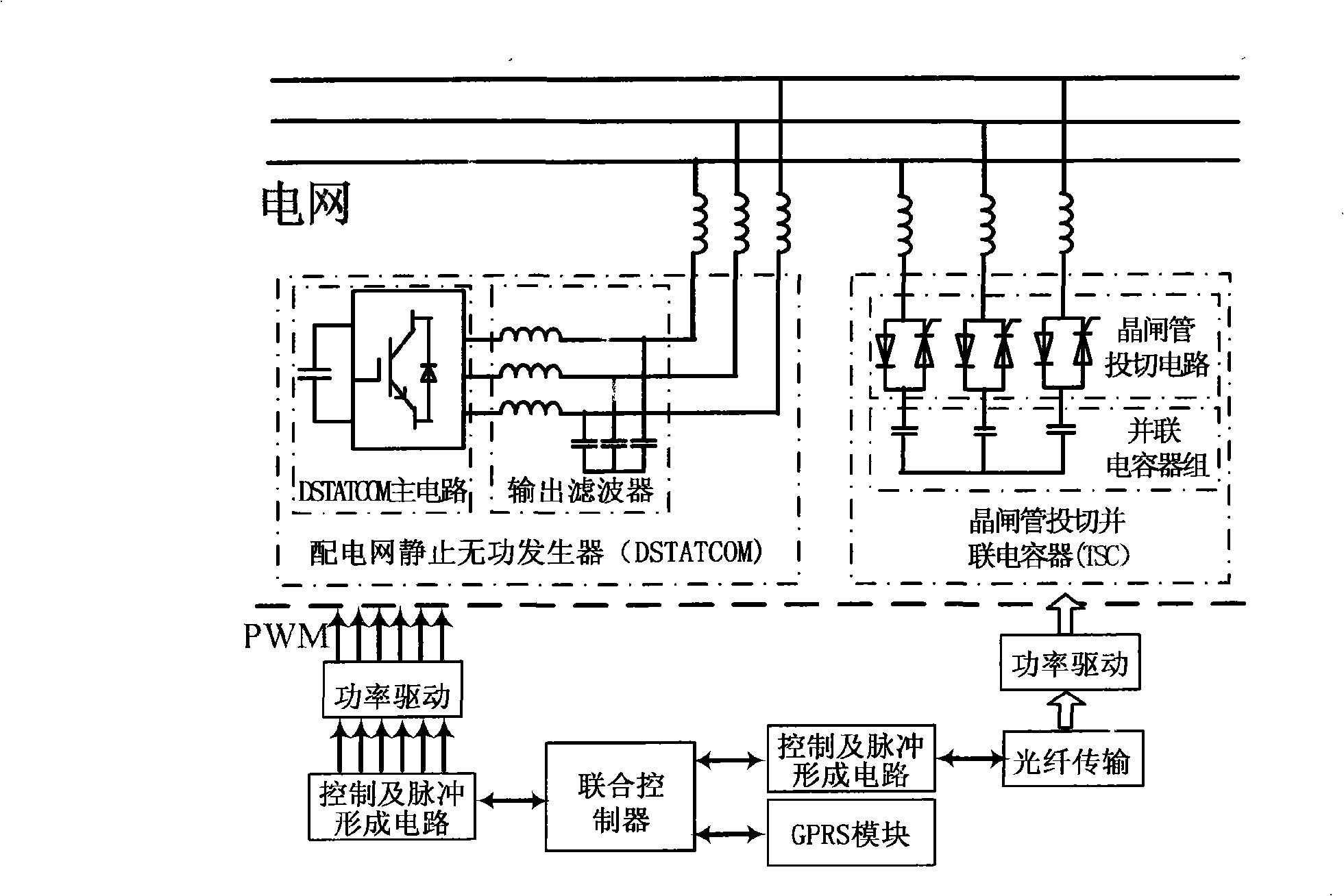
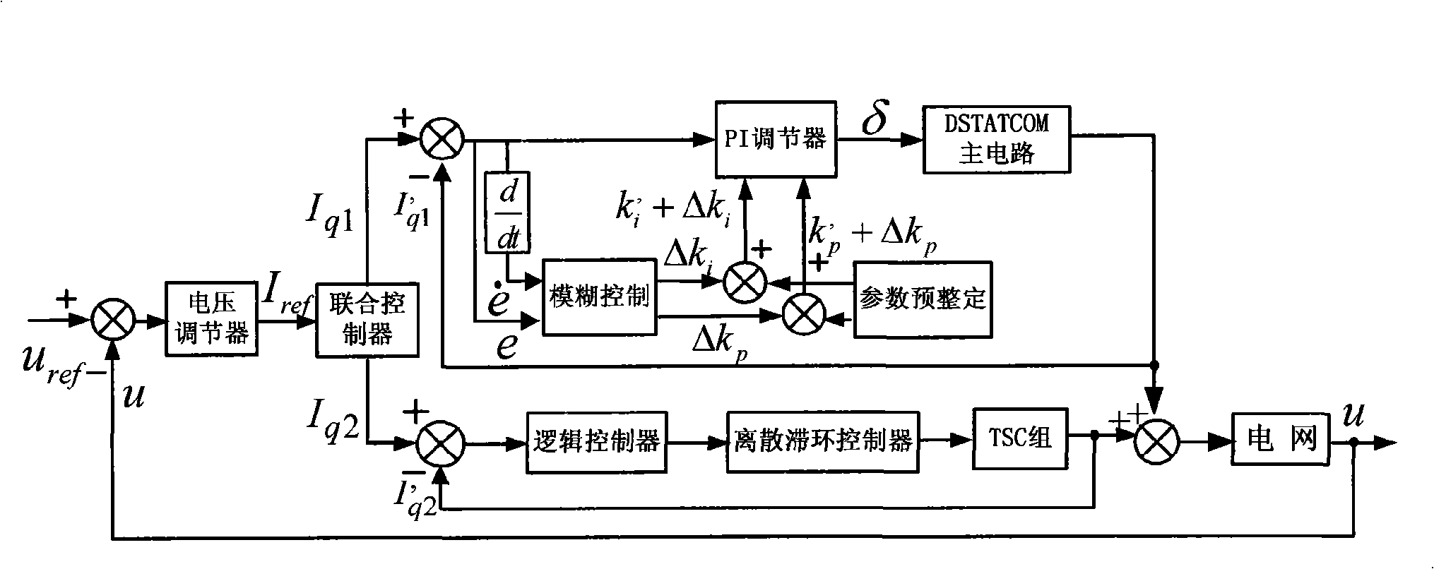
[0024] see figure 1 , the joint control system is mainly composed of joint controller, TSC and DSTATCOM system. The DSTATCOM part is composed of main circuit, output filter circuit, connecting reactor or transformer, control circuit and drive circuit. In the medium and low voltage power distribution system, the main circuit topology of DSTATCOM adopts a single-bridge three-phase voltage inverter, and the capacitor is the energy storage element on the DC side to provide a stable DC voltage for the operation of the inverter. The output voltage of the inverter is hooked up to the power grid through the connected reactor after passing through the filter. When a separate DSTATCOM is used to compensate the power quality problem caused by the reactive current in the load or to improve the voltage quality of the public power supply point, it mainly injects a current that is equal to and opposite to the reactive current component in the load current or Improve the voltage quality at ...


PUM


Abstract

The invention discloses a reactive power optimum compensation system and a control method thereof of a GPRS-based distribution network. The compensation system of the invention comprises a combination control system and an intelligent upper computer (industrial computer) with collaborative optimization control, wherein, the combination control system coordinately controls TSC and DSTATCOM on the same compensation node by a hybrid dynamic control method, and can also realize the data remote-transmission of the system parameters of the node to the intelligent upper computer with collaborative optimization control by a GPRS wireless communication network; the intelligent upper computer with collaborative optimization control searches the optimum compensation node and the compensation capacity by utilizing a multi-machine collaborative reactive power compensation method and also sends an optimum control command to a combination compensation system which then realizes the local large-capacity and continuous reactive power compensation by classified TSC capacitance switching and continuous DSTATCOM compensation. The reactive power optimum compensation system of the invention effectively solves the defects of poor capacity of resisting disturbance and difficult networking, etc. of the existing reactive power compensation system, and also reduces the operation cost.

Description

technical field [0001] The invention relates to a reactive power optimization compensation system and a control method thereof, in particular to a GPRS-based intelligent reactive power optimization compensation system of a power distribution network and a control method thereof. Background technique [0002] With the development of modern science and technology, in recent years, the loads of rectifiers, frequency conversion speed control devices, electric arc furnaces, and electrified railways in distribution networks have continued to increase. The non-linear, impulsive and unbalanced power consumption characteristics of these loads distort the voltage and current waveforms in the network, or cause voltage fluctuations, flicker and three-phase unbalance. Therefore, increasing the power factor of the power grid and stabilizing the system voltage have attracted more and more people's attention. [0003] Thyristor switched capacitors (TSC) are simpler to control, faster in re...

Claims


Application Information

Patent Timeline
Patent Type & Authority Applications(China)
IPC IPC(8): H02J3/18
CPCY02E40/30
Inventor 罗安李强刘秋英赵伟于力黄亮亮
Owner HUNAN UNIV
Learn More