
Air pressure telescopic link

A technology of telescopic rods and air pressure, which is applied in the direction of gas shock absorbers, engine seals, springs, etc., can solve the problems of large automatic changes in the elastic coefficient of springs, the inability to automatically change the expansion and contraction force, and the impact of environmental conditions, etc., to achieve low cost, The spring stretching force can be changed automatically, and the effect is not affected by the climate

Inactive Publication Date: 2008-12-24
周润锡
View PDF1 Cites 1 Cited by
  • Summary
  • Abstract
  • Description
  • Claims
  • Application Information

AI Technical Summary

Problems solved by technology

[0004] The above-mentioned shortcomings are: 1. The spring coefficient of spring changes automatically, breaks, cannot change speed (need to use an external device), cannot automatically change the stretching force, and is affected by environmental conditions, etc.

Method used


Image

  • Air pressure telescopic link
  • Air pressure telescopic link
  • Air pressure telescopic link

Examples


Embodiment Construction

[0017] specific example

[0018] The present invention will be specifically and further described below in conjunction with the accompanying drawings.

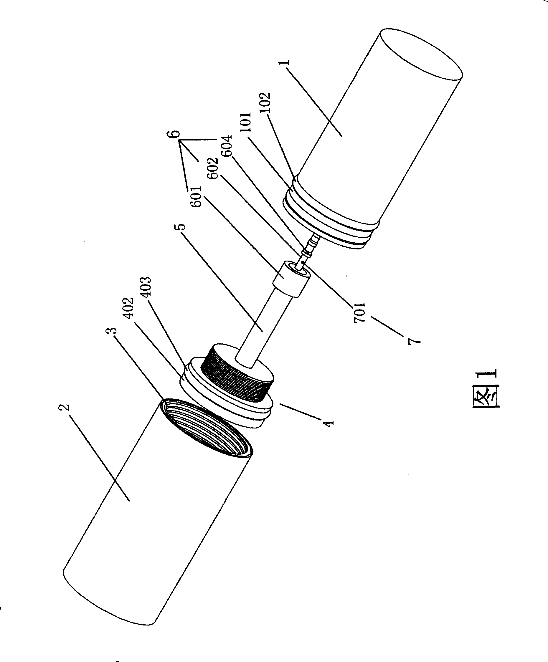
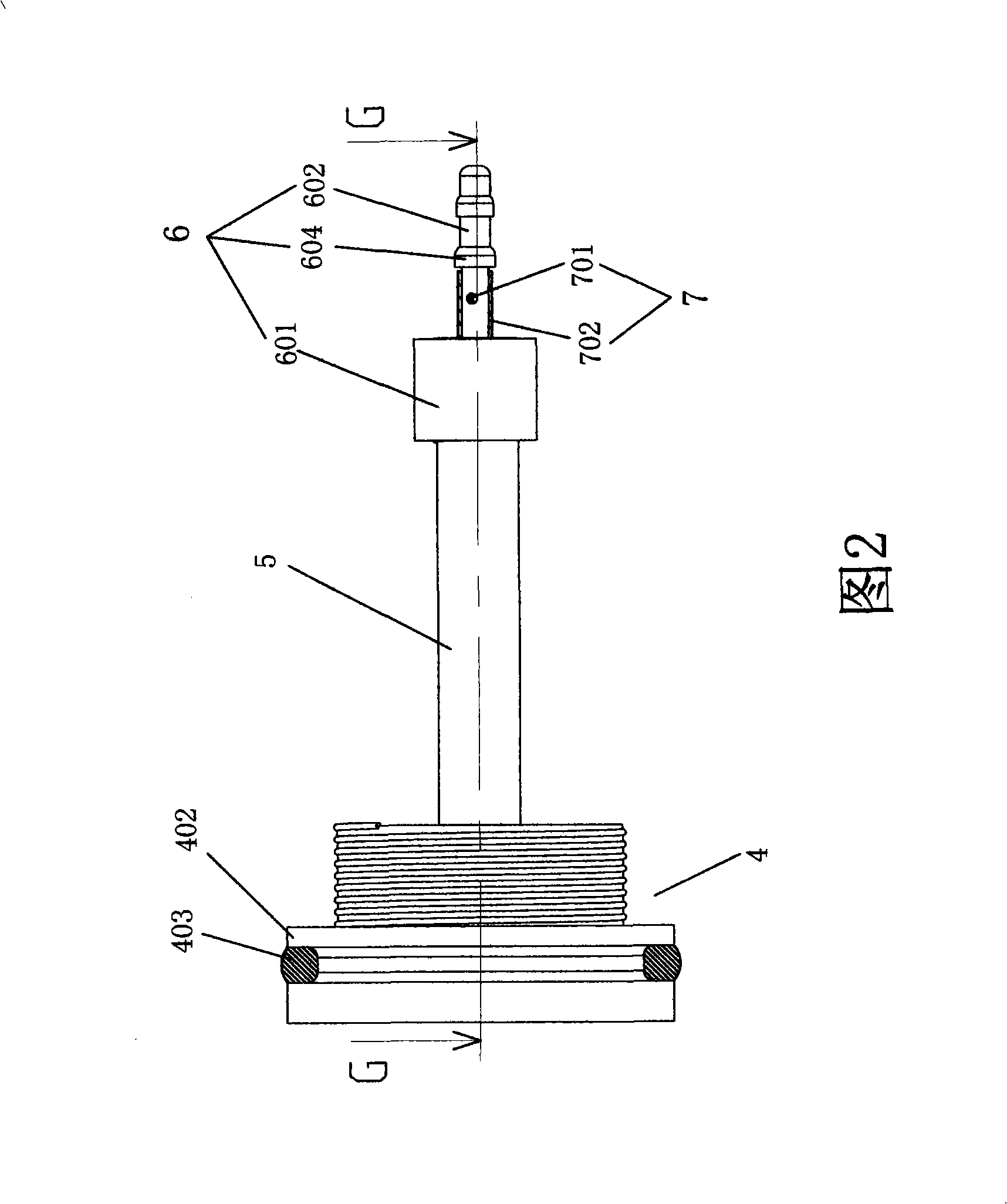
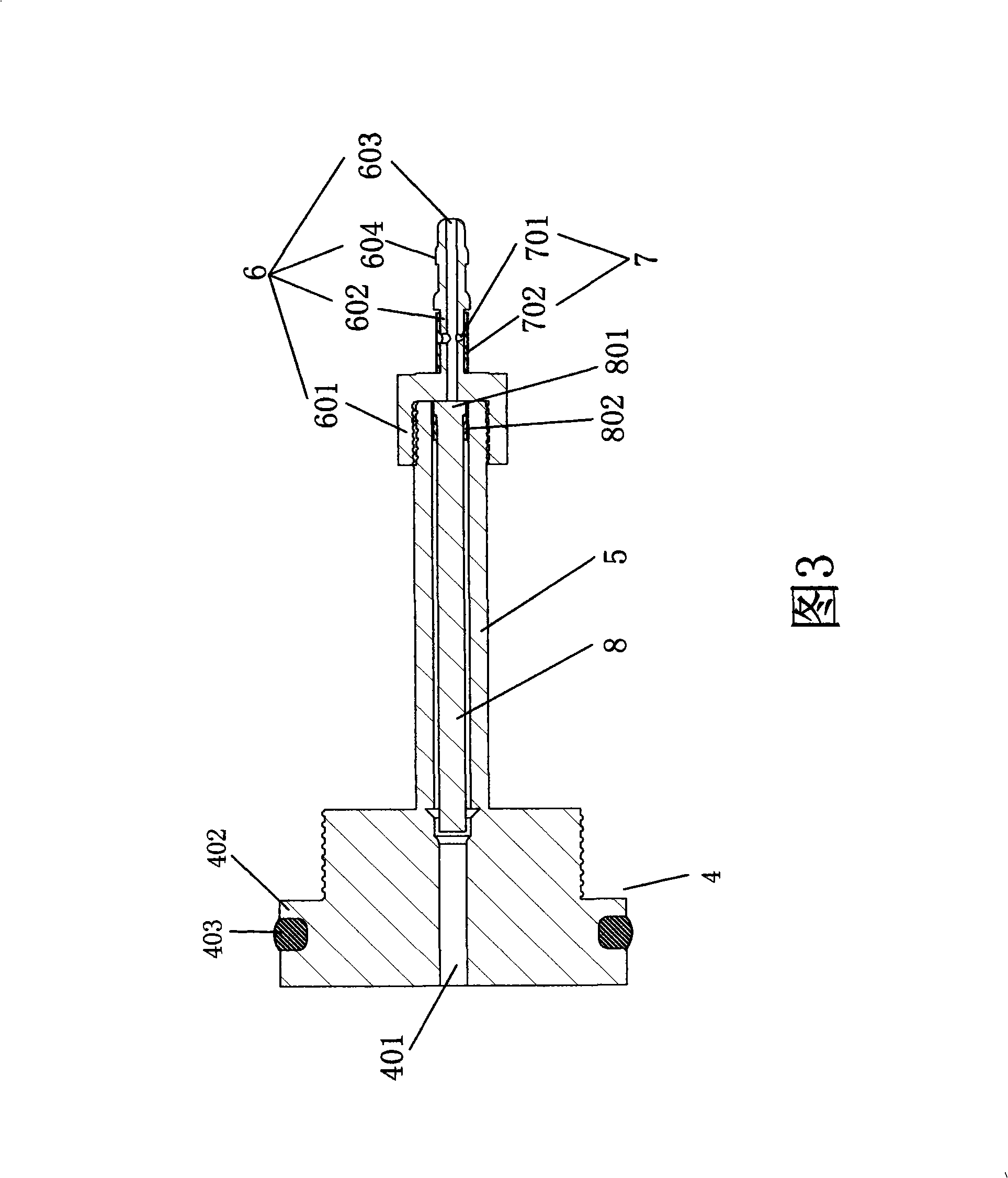
[0019] As shown in the figure, it includes air storage cylinder 1, air cylinder 2 and screw 3. The air storage cylinder 1 is inserted into the cavity of the air cylinder 2, and the screw 3 is set on the air storage cylinder 1 and screwed on the air chamber port of the air cylinder 2. The opening of the air storage cylinder 1 is screwed with a piston 4, the piston 4 is fixedly connected with an air pipe 5, and one end of the air pipe 5 is provided with a throttle valve 6 and a one-way valve 7, and a relevant air needle 8 is placed in the air pipe 5.

[0020] The gas closing needle 8, the throttle valve 6 and the one-way valve 7 are integrated, and the throttle tube 602 is extended from the connecting seat 601, and the related gas needle 8 is placed in the throttle tube 602, and the gas return hole 603 is arranged on the throttl...


PUM


Abstract

The invention particularly relates to a pneumatic expansion link, comprising an air reservoir, an air cylinder and a screw, wherein, the air reservoir is inserted in a chamber of the air cylinder; the screw is sleeved on the air reservoir and is in screwed connection on an air chamber port; an opening of the air reservoir is in screwed connection with a piston which is fixedly connected with an air pipe; one end of the air pipe is provided with a throttle valve and a one-way valve; and an air shutter needle is arranged in the air pipe. The invention has the advantages of pure air pressure, constant motion, oil omission, automatic variation of spring elasticity, adjustable speed reduction, weather resistant, low cost, simple process, long service life and so on.

Description

technical field [0001] The invention specifically relates to a pneumatic expansion rod. Background technique [0002] The original spring and gas spring are divided into two categories. The current market is popular that the spring is made of steel wire, which has the advantages of simple structure and low cost. The patent number is 200620058318.6. Its structure is as follows: there is an outer casing with a head at one end, and an inner casing with a head at one end is movably sleeved in the outer casing. A connecting mechanism connects the outer casing and the inner casing. The connecting mechanism is a long Spring, the long spring is located in the inner casing and the outer casing, one end of the long spring is fixedly connected to the end near the top in the outer casing, and the insertion end of the inner casing is horizontally provided with a pin, which passes through the long spring. [0003] The other is an air spring, which is composed of a steel wire wound spring...

Claims


Application Information

Patent Timeline
IPC IPC(8): F16F9/02F16F9/34F16F9/32F16J15/16
Inventor 王春生
Owner 周润锡
Learn More