Method for sieving pendulum shaft and pendulum shaft sieving machine thereof

A screening and sieve surface technology, which is applied in chemical instruments and methods, sieves, solid separation, etc., can solve the problem of high cost of screen body, high cost of equipment and wearing parts, and deterioration of screening efficiency, etc. problems, to achieve the effect of low vibration and noise, reliable performance and simple structure

Active Publication Date: 2008-12-24
姚劲
View PDF0 Cites 3 Cited by
  • Summary
  • Abstract
  • Description
  • Claims
  • Application Information

AI Technical Summary

Problems solved by technology

However, when the material to be sieved is relatively wet and contains a certain amount of mud (sticky wet material), the sieve holes of the first two methods are easy to stick to death, and the material falls with the sieve surface at the same time or is thrown up at the same time and is easy to stick to agglomerates, and the screening efficiency is sharply reduced. Deterioration; due to the complex structure of the transmission part, the opening ratio of the sieve plate is limited by the axial distance and the cost of the sieve body is high. Generally, it is only used for screening materials with large particle size (particle size > 30mm)
The screening effect of the spiral screen is better, but the power consumption is large (2-3 times that of ordinary screening), the cost of equipment and wearing parts is high, and it has a crushing effect on materials, so it is rarely used at present.

Method used


Image

  • Method for sieving pendulum shaft and pendulum shaft sieving machine thereof
  • Method for sieving pendulum shaft and pendulum shaft sieving machine thereof
  • Method for sieving pendulum shaft and pendulum shaft sieving machine thereof

Examples


Embodiment Construction

[0028] Further describe the present invention in detail below in conjunction with accompanying drawing and specific embodiment:

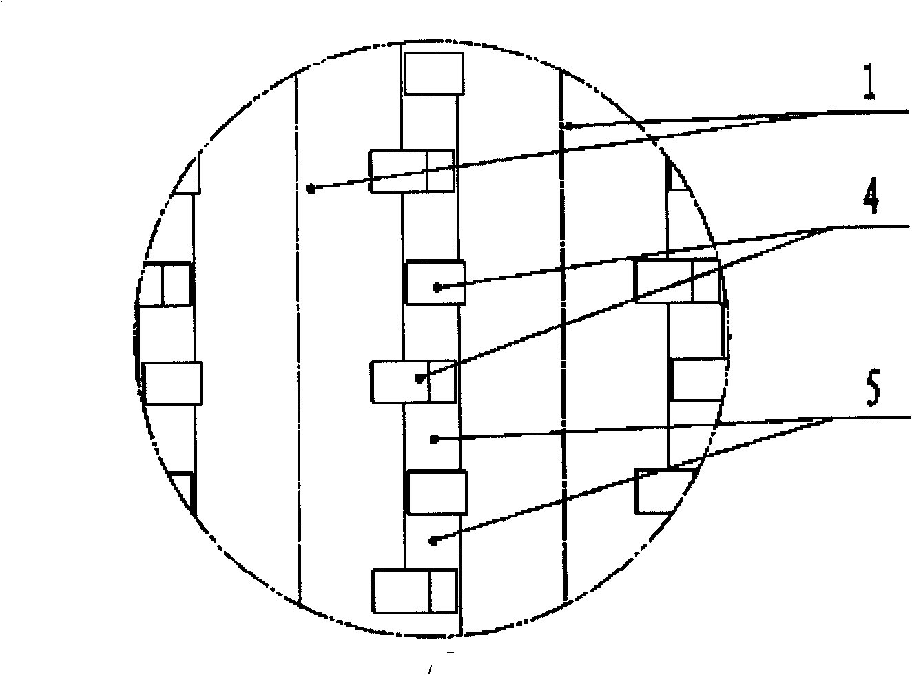
[0029] As shown in Fig. 1 and Fig. 2, the pendulum screening machine of the present invention includes a screen surface 2 and a screen hole 5, and a plurality of pendulum shafts 1 are installed side by side on the screen surface 2 frame, and two opposite pendulum shafts 1 on each pendulum shaft 1 The side is provided with a plurality of fins 4, and the fins 4 on adjacent shafts 1 are arranged in a staggered manner (such as image 3 ), the gap between the adjacent shaft 1 and the gap between the wings 4 on the adjacent shaft 1 constitutes a sieve hole 5 (such as Figure 4 ).

[0030] A pendulum screening method according to the present invention, the specific embodiment is to install a plurality of pendulum shafts 1 side by side on the frame of the screen surface 2, the gap between adjacent shafts 1 is the size of one direction of the sieve hole 5, a...


PUM


Abstract

The invention relates to a screening method and a screening device used for coal dressing and ore dressing, in particular to a pendulum shaft screening method and a pendulum shaft screening machine thereof. The machine consists of a screening surface, sieve pores and a plurality of pendulum shafts arranged side by side on the screening surface frame, wherein a plurality of wings are correspondingly arranged on each pendulum shaft; the wings on adjacent shafts are arranged in a staggered way; clearances between the adjacent shafts and clearances between the wings on the adjacent shafts form the sieve pores. Particles of large size in the materials to be screened are tossed up by the wings on the pendulum shafts, while the materials of fine particle size run through the clearances between the materials and are leaked through the clearances between the adjacent shafts onto the wings, and then are leaked through the sieve pores formed by the clearances between the adjacent shafts and the wings on the adjacent shafts to below the screen, achieving the screening operation. The screening device has the advantages of simple structure, convenient maintenance, non-vibration of the screening frame, low energy consumption, high efficiency, less noise and vibration, flexibility in layout; and compared with vibrating screen, the device also has the advantages of solid structure, silent work, reliable performance, and the advantage that the screened materials can be extremely easily collected. The device is especially applicable for the screening of crude coal and various sticky materials.

Description

Technical field [0001] The invention relates to a screening method and screening equipment for coal preparation and ore dressing, in particular to a pendulum screening method and a pendulum screening machine. Background technique [0002] At present, the commonly used screening methods and screening equipment for mineral processing and coal preparation at home and abroad include: vibrating screen, shaking screen, roller screen, spiral screen, etc. The first two types use the vibration of the sieve plate or the entire sieve body to project and loose materials, while the latter two types use shaft rotation to convey and screen materials, and in most cases can achieve ideal results. However, when the material to be sieved is relatively wet and contains a certain amount of mud (sticky wet material), the sieve holes of the first two methods are easy to stick to death, and the material falls with the sieve surface at the same time or is thrown up at the same time and is easy to st...

Claims


Application Information

Patent Timeline
IPC IPC(8): B07B1/15B07B1/42B07B1/46
Inventor 姚劲王赛宇
Owner 姚劲
Why Eureka
Try Eureka