Hydraulic pipe drawing device

A hydraulic and hydraulic system technology, applied in the field of construction equipment, can solve problems such as the inability to achieve height and the impact of large-scale production, and achieve the effects of large pulling force, simple structure and convenient movement.

Inactive Publication Date: 2008-12-17
DALIAN GREAT GOLDEN HORSE INFRASTRUCTURE
View PDF0 Cites 2 Cited by
  • Summary
  • Abstract
  • Description
  • Claims
  • Application Information

AI Technical Summary

Problems solved by technology

[0002] At present, the construction cast-in-place piles are mainly artificial hole-digging cast-in-place piles and mechanical hole-forming mud wall-protecting cast-in-place piles. There are many deficiencies in these two methods. Therefore, the inventor designs a kind of cast-in-place pile that utilizes large-diameter steel pipes to form holes. method, but large-diameter steel pipes need to be lifted and pulled when pouring concrete, and the current equipment cannot realize the lifting and pulling of steel pipes with large heights and large diameters to realize the reuse of steel pipes, so the large-scale production of this advanced construction method influence

Method used


Image

  • Hydraulic pipe drawing device
  • Hydraulic pipe drawing device

Examples


Embodiment Construction

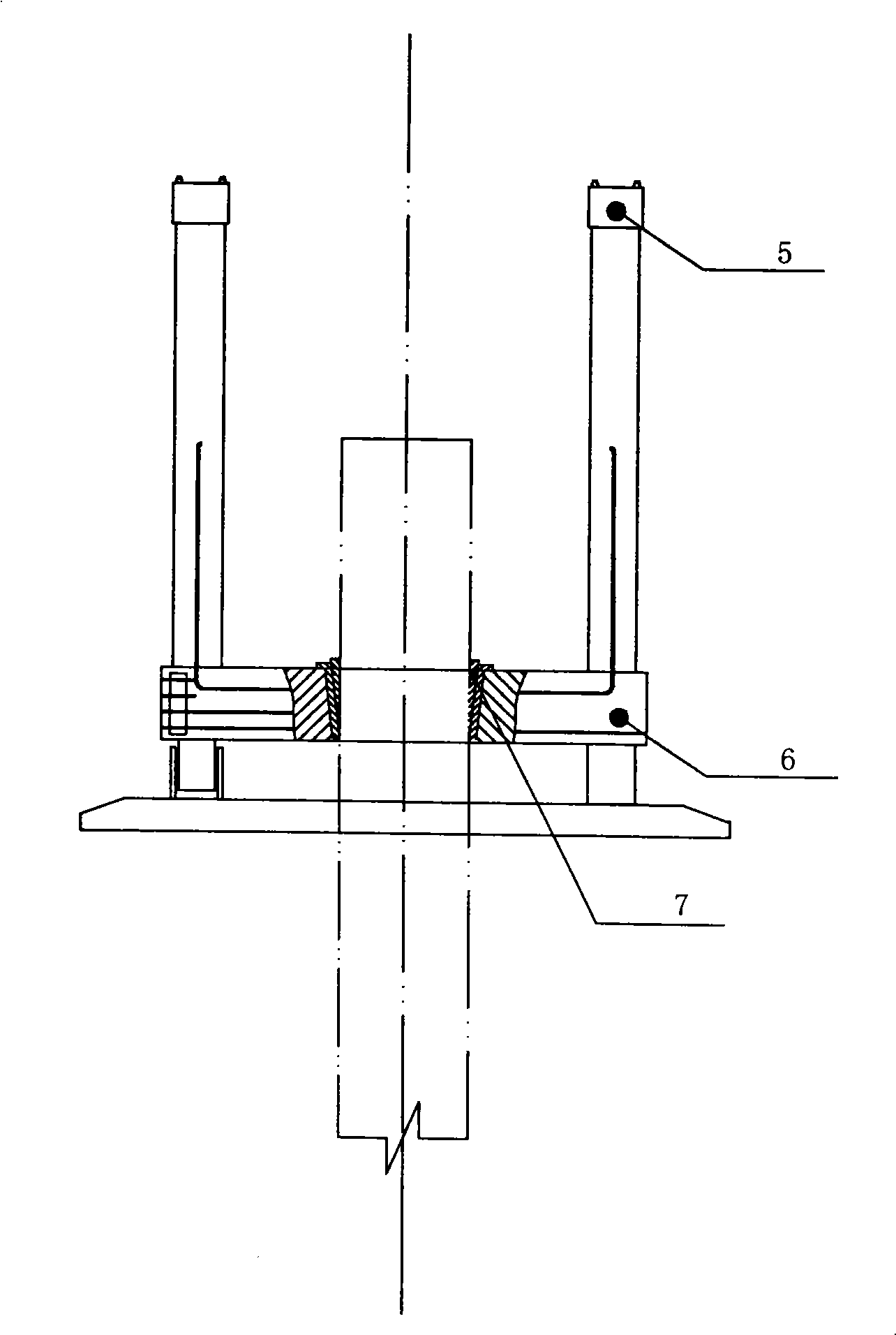
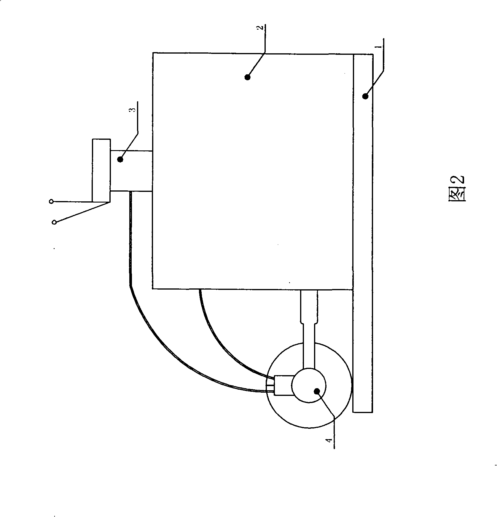
[0011] Such as figure 1 The hydraulic extubation device shown in and 2 is composed of a hydraulic system and an extubator. The hydraulic system is shown in Figure 2. The hydraulic oil tank 2 is fixed on the bracket 1. The oil outlet of the hydraulic oil tank is equipped with an oil pump 4, and the outlet of the oil pump is connected to distribute Distributor 3, the distributor communicates with the hydraulic cylinder 5, the arm of the hydraulic cylinder is equipped with an extubation frame 6, the extubation frame has an assembly hole, and is set on the cylinder arm through the assembly hole, there is a large steel pipe socket in the middle of the extubation frame, and the socket It is locked with the large steel pipe by the locking device 7, the locking device is an inclined iron, and the hydraulic station supplies 30mpa hydraulic oil. Oil is supplied up and down to the tube puller cylinder through the distributor to realize the up and down movement of the cylinder arm.


PUM


Abstract

The invention provides a hydraulic pipe drawing device, relating to the field of building construction. The hydraulic pipe drawing device consists of a hydraulic system and a pipe drawing device; the hydraulic ram arm of the hydraulic system is provided with a pipe drawing frame; the middle part of the pipe drawing frame is provided with a large steel pipe insertion hole; the insertion hole and the large steel pipe are locked firmly by a locking device. The hydraulic pipe drawing device of the invention is corollary equipment of the construction method for the impact-typed large-diameter steel pipe pore-forming pouring pipe. The hydraulic pipe drawing device has simple structure, large upper drawing force and convenient movement; especially the steel pipe is clamped firmly by tapered iron; therefore, the hydraulic pipe drawing device has the greatest advantages that the greater the upper drawing resistance of the steel pipe is, the greater the claming force is, thus leading the steel pipe punched into the ground with extremely large upper drawing resistance to be pulled out easily.

Description

1. Technical field: [0001] The invention relates to the field of building construction, in particular to building construction equipment. 2. Background technology: [0002] At present, the construction cast-in-place piles are mainly artificial hole-digging cast-in-place piles and mechanical hole-forming mud retaining wall cast-in-place piles. There are many deficiencies in these two methods, so the inventor designs a kind of cast-in-situ pile construction utilizing large-diameter steel pipes to form holes. method, but the large-diameter steel pipe needs to be lifted and pulled when pouring concrete, and the current equipment cannot realize the lifting and pulling of the steel pipe with a large height and large diameter to realize the reuse of the steel pipe, so the large-scale production of this advanced construction method influence. 3. Contents of the invention: [0003] The object of the present invention is to overcome the above disadvantages and provide a hydraulic e...

Claims


Application Information

Patent Timeline
Patent Type & Authority Applications(China)
IPC IPC(8): E02D9/02
Inventor 徐世大
Owner DALIAN GREAT GOLDEN HORSE INFRASTRUCTURE
Why Eureka
Try Eureka