
Head-mounted display capable of adjusting surroundings light intensity

A display and head-mounted technology, applied in the field of optical vision devices, can solve problems such as increasing manufacturing costs

Inactive Publication Date: 2008-12-10
HIMAX DISPLAY INC
View PDF1 Cites 19 Cited by
  • Summary
  • Abstract
  • Description
  • Claims
  • Application Information

AI Technical Summary

Problems solved by technology

[0005] However, using an LCD shutter will greatly increase the manufacturing cost. It is obviously not worth using an expensive LCD shutter if it is only for switching between see-through and non-see-through modes
Therefore, it is necessary to provide a head-mounted display, which can replace the liquid crystal shutter with a cheaper and simpler switching component, so as to overcome the above-mentioned defects of high cost

Method used

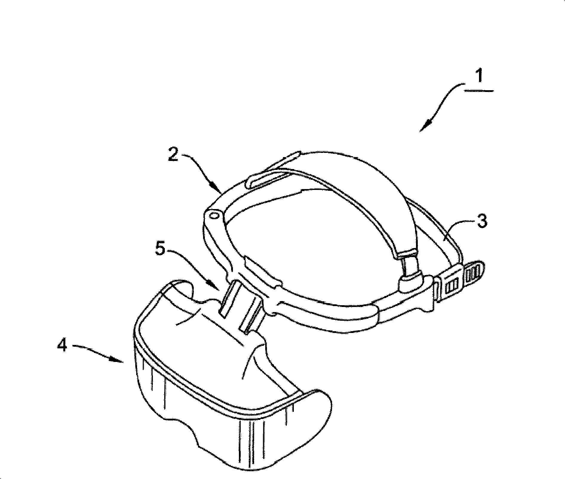

Image

  • Head-mounted display capable of adjusting surroundings light intensity
  • Head-mounted display capable of adjusting surroundings light intensity
  • Head-mounted display capable of adjusting surroundings light intensity

Examples


Embodiment Construction

[0016] The invention will be more apparent from this embodiment with reference to the description of the head-mounted display 1 and its optical visualization unit 4 provided below with reference to the accompanying figures.

[0017] figure 1 Shown is a schematic diagram of a head-mounted display 1 according to an embodiment of the present invention. As shown in the figure, the head-mounted display 1 includes a main body 2, which can be connected to a remote controller wirelessly or by wire (not shown). The main body 2 includes a head-mounted unit 3 for wearing the main body 2 on the viewer's head; and an optical visualization unit 4 connected with the head-mounted unit 3 through a connecting unit 5 . The head-mounted unit 3 is designed so that the optical visualization unit 4 can be worn in front of the viewer.

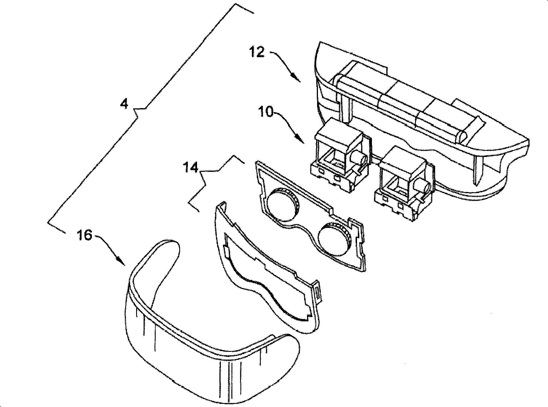
[0018] figure 2 is an exploded view of the optical visualization unit 4 according to an embodiment of the present invention. As shown in the figure, the optical ...


PUM


Abstract

A head-mounted display is provided with a main body which is connected with a remote manipulator and is provided with an optical visualization unit. The optical visualization unit comprises a display element which is used for displaying virtual images, a housing which is used for containing the display element, a polarization element which is arranged in the front of the housing and used for adjusting the ambient light intensity of the display element, and a front cover element which is used for covering the front surface of the housing. The polarization element can shift between a perspective mode and a non-perspective mode under the control of the user.

Description

technical field [0001] The invention relates to an optical vision device; in particular, it relates to a head-mounted display. Background technique [0002] A head-mounted display (HMD) is an optical visualization device that uses display components to display virtual images in front of the user's eyes. Such devices are widely used in the field of virtual reality (VR) technology. In some cases, people need virtual images to enhance their senses of the real world. This method is called "augmented reality". on the scene. The simpler approach is to use optical see-through design to allow ambient light to enter the semi-reflective and semi-transmissive screen; while the more complex video see-through design is to first transform light into video and then combine it with virtual images for display. [0003] Optical see-through head-mounted displays are not ideal given the need for information under the display to be protected from exposure. Of course, non-perspective designs ...

Claims


Application Information

Patent Timeline
IPC IPC(8): G02B27/01G02B26/00G02B5/30
Inventor 吴炳升陈燕晟陈坤泰李国永
Owner HIMAX DISPLAY INC
Learn More