Assembly method for reducing timing error of car engine

A technology of automobile engine and assembly method, which is applied in the direction of engine components, machines/engines, valve devices, etc., can solve problems such as phase errors, and achieve the effect of reducing timing errors

Inactive Publication Date: 2008-12-10
CHERY AUTOMOBILE CO LTD
View PDF0 Cites 2 Cited by
  • Summary
  • Abstract
  • Description
  • Claims
  • Application Information

AI Technical Summary

Problems solved by technology

However, since there is no positioning requirement between the camshaft timing gear and the camshaft, and the tensioner is arranged on the loose side of the belt, in the process of tightening the camshaft bolts, due to the friction torque of the bolts, the camshaft gear and the camshaft The relative rotation of the camshaft causes a certain phase error

Method used


Image

  • Assembly method for reducing timing error of car engine

Examples


Embodiment Construction

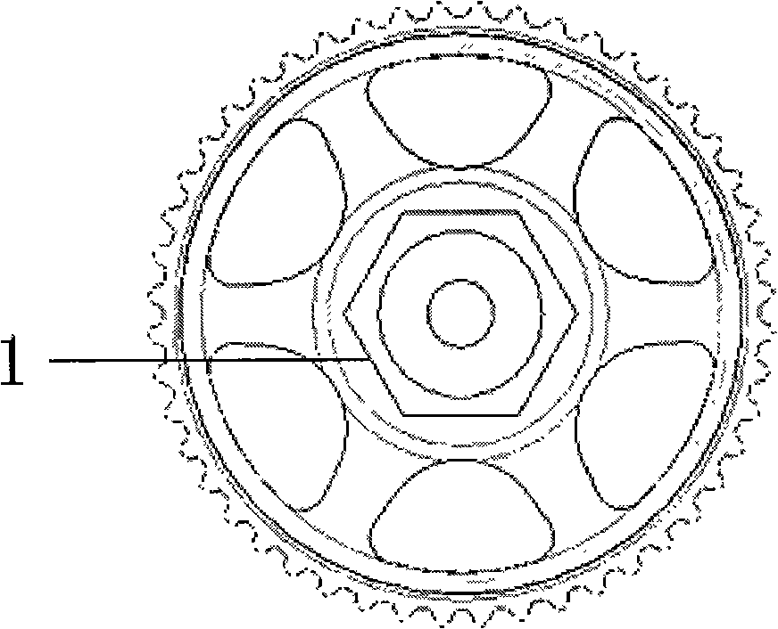
[0012] The assembly method is, after fixing the crankshaft and camshaft, assemble the crankshaft, camshaft timing gear, tensioner and idler, install the timing belt, and finally tighten the bolts of the camshaft timing gear, after tightening the camshaft timing gear During the bolting process, ensure that the timing gear and the camshaft do not rotate relative to each other.

[0013] As shown in the figure, the non-relative rotation between the timing gear and the camshaft is achieved by the following method: the camshaft timing gear has an extra hexagonal flange surface 1, and when tightening the bolts of the camshaft timing gear, use the timing tool to pass through The timing gear is fixed by the hexagonal flange surface to ensure that the camshaft timing gear and the camshaft do not rotate relative to each other during the tightening of the camshaft timing gear bolts, thereby reducing the timing error.


PUM


Abstract

The invention relates to an assembly method of an automobile engine for reducing timing error, which can effectively reduce the timing error. The technical proposal is as follows: in the assembly method of an automobile engine for reducing timing error, after a crank shaft and a cam shaft are fixed, crank shaft and cam shaft timing gears, a tensioner and an idler wheel are assembled, a timing timming belt is arranged, and finally a cam shaft timing gear bolt is screwed up; the method is characterized in that when the cam shaft timing gear bolt is screwed up, no relative rotation of the timing gear and the cam shaft is ensured.

Description

technical field [0001] The invention relates to an assembly method for reducing timing error of an automobile engine. Background technique [0002] The automobile engine timing system is an important system that transmits the driving force of the crankshaft to the camshaft. It ensures that the intake and exhaust valves of the engine are opened and closed according to the designed angular position, and ensures the normal operation of the engine valve train. [0003] Now widely used automobile engine timing system is to rely on the timing belt to transmit power from the crankshaft timing gear to the camshaft timing gear, and the timing belt structure is a synchronous toothed belt. Existing designs generally use an automatic tensioner, and the tensioner is arranged on the loose side of the belt. The timing method is generally to fix the crankshaft and camshaft to ensure the phase of the crankshaft and camshaft; install the timing belt; fix the automatic tensioner, and finally ...

Claims


Application Information

Patent Timeline
IPC IPC(8): F01L1/348
Inventor 马自立张德定
Owner CHERY AUTOMOBILE CO LTD
Why Eureka
Try Eureka