Capacitor
A technology of capacitors and electrodes, which is applied in the field of capacitors and can solve problems such as inability to connect multiple capacitors and increased resistance
- Summary
- Abstract
- Description
- Claims
- Application Information
AI Technical Summary
Problems solved by technology
Method used
Image
Examples
no. 1 approach
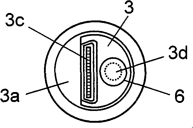
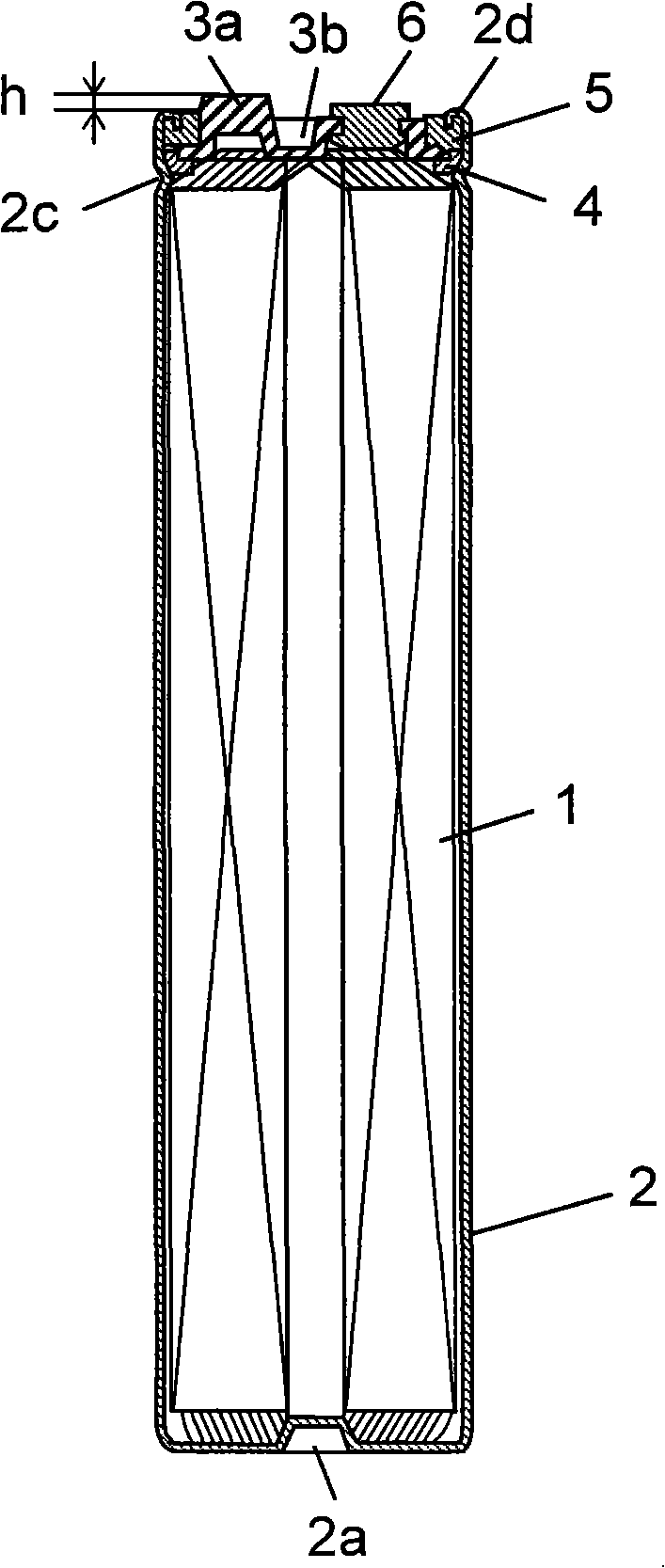
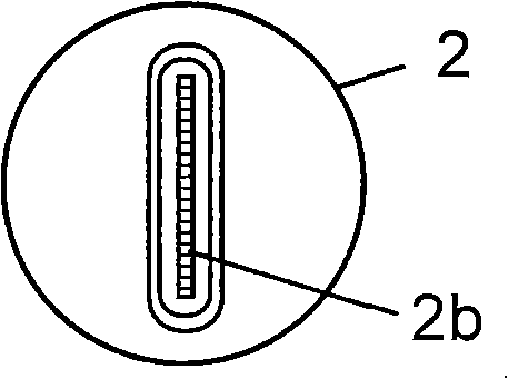
[0072] Figure 1A , Figure 1B , Figure 1C It is a plan view, a front cross-sectional view, and a bottom view showing the structure of the capacitor according to the first embodiment of the present invention. like Figure 1A , Figure 1B , Figure 1C As shown, the capacitor has a capacitor element 1 . Then, a pair of positive and negative electrodes in which a polarizable electrode layer is formed on a current collector made of metal foil such as aluminum foil are rolled at positions shifted in opposite directions, with separators (all not shown) interposed therebetween and rolled. winding, thereby constituting the capacitor element 1, from the two end faces of the capacitor element 1 ( Figure 1B The top and bottom in the ) lead out the anode and cathode respectively. That is, the capacitor element 1 is constituted by exposing one ends of the positive and negative electrodes in opposite directions, respectively.
[0073] Further, the capacitor includes an aluminum bo...
no. 2 approach
[0083] The second embodiment is configured by providing two connecting portions provided on the terminal plate of the capacitor described in the first embodiment on the peripheral edge of the terminal plate. The same parts are denoted by the same symbols, and detailed descriptions thereof will be omitted, and only different parts will be described below with reference to the drawings.
[0084] Figure 4A , Figure 4B , Figure 4C It is a plan view, a front cross-sectional view, and a bottom view showing the structure of the capacitor according to the second embodiment of the present invention. 5A, 5B, and 5C are a plan view, a front sectional view, and a bottom view showing a state in which two capacitors are connected. The capacitor of the second embodiment is constituted by an example of a large-sized large-capacity (high-current) type capacitor. of.
[0085] like Figure 4A , Figure 4B , Figure 4C As shown, the capacitor has a metal case 10 and a concave portion 10...
no. 3 approach
[0090] In this embodiment, the connection portion provided on the terminal plate of the capacitor described in the first embodiment is provided in the center of the terminal plate, and the structure other than that is the same as that of the first embodiment, so the same parts are given the same , the detailed description thereof is omitted, and only the different parts will be described below with reference to the drawings.
[0091] Figure 6A , Figure 6B , Figure 6C It is a plan view, a front cross-sectional view, and a bottom view showing the structure of the capacitor according to the third embodiment of the present invention. like Figure 6BAs shown, the capacitor of the third embodiment includes a metal case 15 and a recess 15 a provided on the bottom surface of the metal case 15 . And, the electrode exposed on one end surface of the capacitor element 1 is crimped on the inner surface of the recessed part 15a, and is connected by methods such as welding by irradiat...
PUM
 Abstract
Description
Claims
Application Information
 - R&D
- Intellectual Property
- Life Sciences
- Materials
- Tech Scout
- Unparalleled Data Quality
- Higher Quality Content
- 60% Fewer Hallucinations
Browse by: Latest US Patents, China's latest patents, Technical Efficacy Thesaurus, Application Domain, Technology Topic, Popular Technical Reports.
© 2025 PatSnap. All rights reserved.Legal|Privacy policy|Modern Slavery Act Transparency Statement|Sitemap|About US| Contact US: help@patsnap.com


