
Multilayer capacitor

A technology of stacked capacitors and capacitors, which is applied in the direction of multilayer capacitors, fixed capacitor dielectrics, and structurally fixed capacitor combinations, etc., can solve the problems of high frequency side characteristic degradation, and the band domain of impedance cannot be widened, and achieves high ESR and realization. The effect of ESR and low ESL

Active Publication Date: 2008-11-19
MURATA MFG CO LTD
View PDF2 Cites 4 Cited by
  • Summary
  • Abstract
  • Description
  • Claims
  • Application Information

AI Technical Summary

Problems solved by technology

[0005] However, according to the structure described in Patent Document 2, although the ESR can be improved, the ESL is also improved accordingly, and compared with the case described in Patent Document 1, there is a problem that the characteristics on the high frequency side are degraded.
[0006] In addition, according to the multilayer capacitor described in Patent Document 2, the frequency-impedance characteristic is substantially unchanged from the case of Patent Document 1 in the band where the impedance can be reduced because the resonance point is shifted only to the low frequency side. Cannot widen the band that can reduce the impedance

Method used


Image

  • Multilayer capacitor
  • Multilayer capacitor
  • Multilayer capacitor

Examples


Embodiment Construction

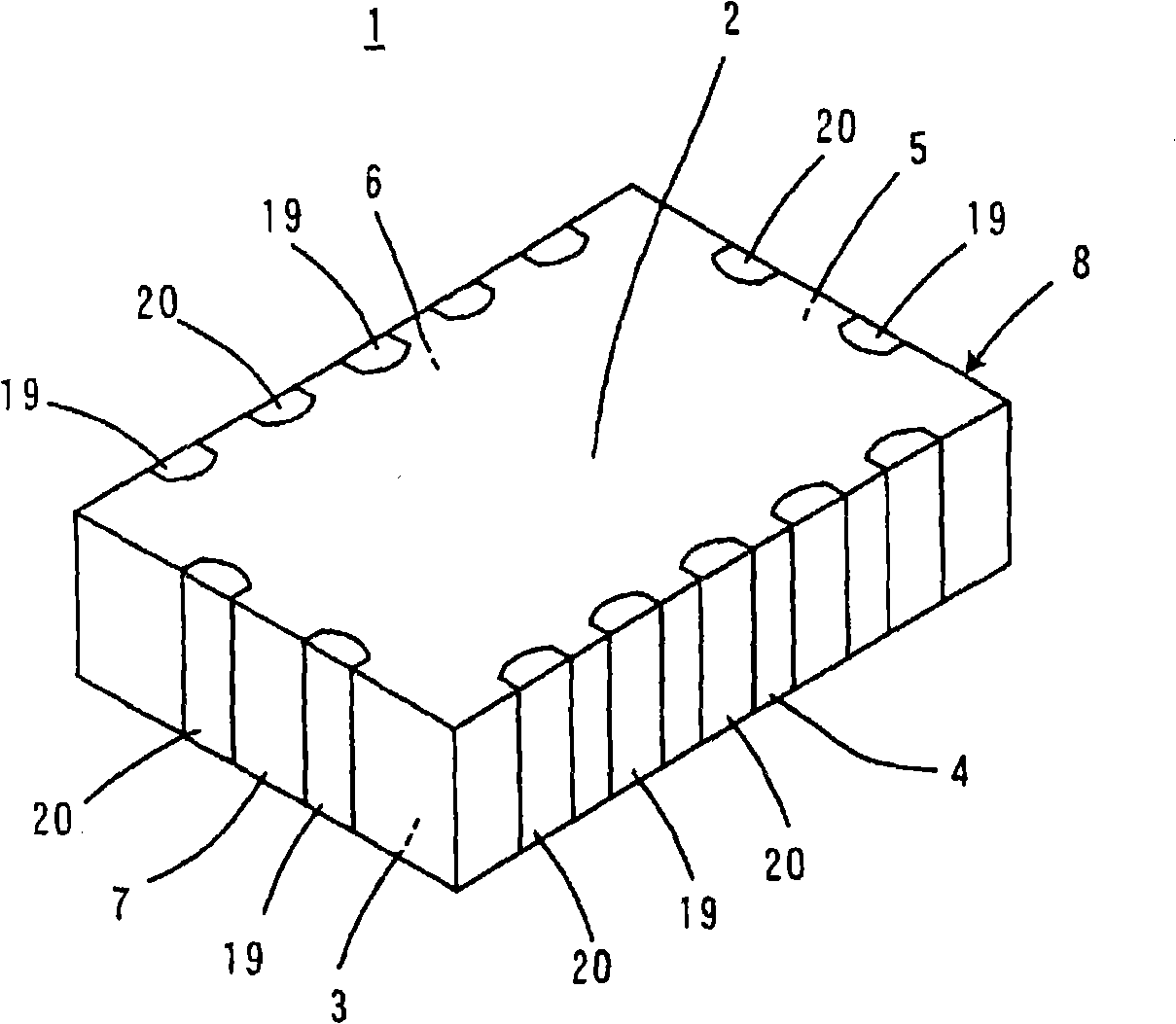
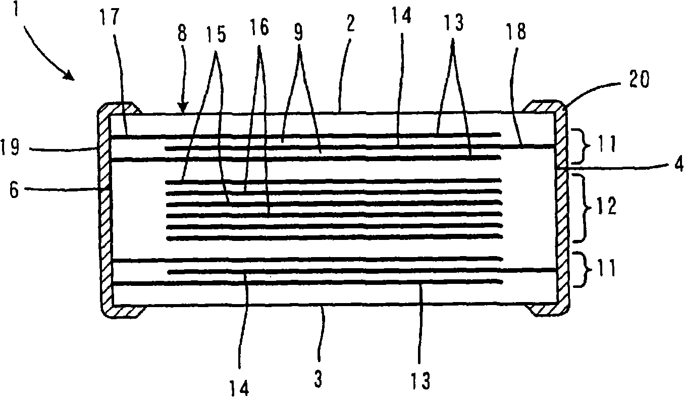
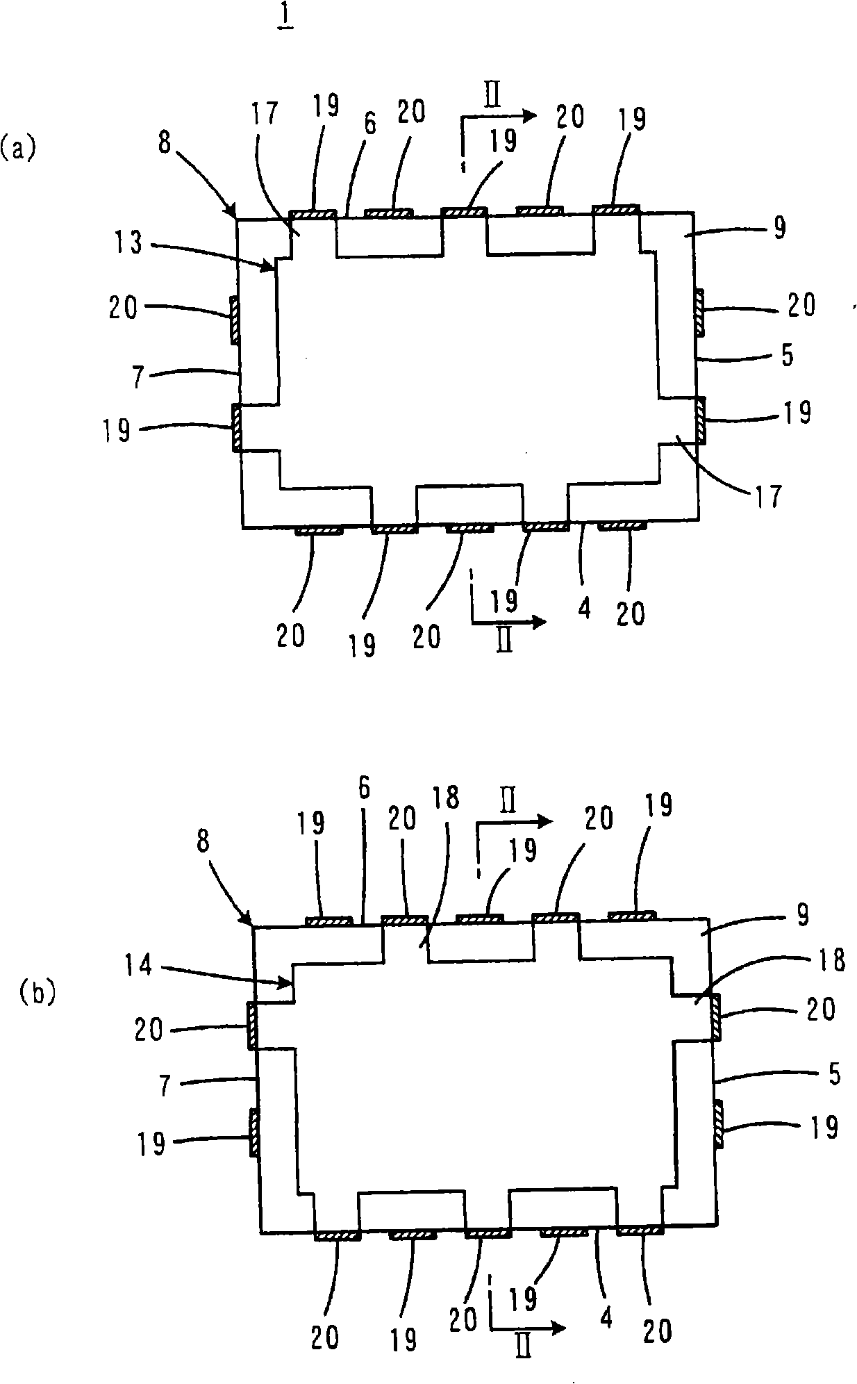
[0043] Figure 1 to Figure 4 Multilayer capacitor 1 according to one embodiment of the present invention is shown. here, figure 1 is a perspective view showing the appearance of the multilayer capacitor 1, figure 2 It is a front view showing the internal structure of the multilayer capacitor 1 . in addition, figure 2 , the multilayer capacitor 1 follows the later-described image 3 and Figure 4 The cross-section representation of the line II-II.

[0044] Multilayer capacitor 1 includes a cube-shaped capacitor body 8 having two opposing main surfaces 2 and 3 and four side surfaces 4 , 5 , 6 and 7 connecting the two main surfaces 2 and 3 . The capacitor main body 8 has a laminated structure including a plurality of laminated dielectric layers 9 made of, for example, dielectric ceramics and extending in the directions of the main surfaces 2 and 3 .

[0045] Capacitor body 8 as figure 2 As shown, the first and second capacitor parts 11 and 12 are formed. In this embod...


PUM


Abstract

The invention provides a multilayer capacitor. On a capacitor body (8), a first capacitor portion (11) and a second capacitor portion (12) are arranged in parallel in the layered direction. While setting the resonance frequency of the first capacitor portion (11) higher than that of the second capacitor portion (12) so that the first capacitor portion (11) contributes to low ESL, ESR of each layer of the second capacitor portion (12) is set higher than ESR of each layer of the first capacitor portion (11) so that the second capacitor portion (12) contributes to high ESR. Furthermore, combined ESR of the first capacitor portion (11) is set equal to or substantially equal to the combined ESR of the second capacitor portion (12), thus realizing low ESL and high ESR, and widening the zone capable of reducing resistance.

Description

technical field [0001] The present invention relates to stacked capacitors, and more particularly to stacked capacitors designed to be advantageously used in high frequency circuits. Background technique [0002] In a high-frequency region such as several GHz, as a decoupling capacitor used in a power supply circuit such as an MPU (microprocessor), for example, that described in JP-A-11-144996 (Patent Document 1) is known. A structured stacked capacitor. According to this multilayer capacitor, by making a multi-terminal structure and reversing the polarity of adjacent terminals, the flow of current from the positive electrode to the negative electrode is shortened, the flow of current is varied, and the directions of the currents are directed in opposite directions, so that The magnetic fluxes cancel each other out, thereby achieving a reduction in ESL (equivalent series inductance). [0003] However, according to the multilayer capacitor described in the above-mentioned P...

Claims


Application Information

Patent Timeline
Patent Type & Authority Applications(China)
IPC IPC(8): H01G4/30H01G4/12
CPCH01G4/30H01G4/40H01G4/12
Inventor 高岛宽和上冈浩高木义一
Owner MURATA MFG CO LTD
Learn More