
Diode electrical characteristics test system

A test system and diode technology, applied in the direction of single semiconductor device testing, etc., can solve the problems of affecting accuracy, large additional loss, and difficulty in characterization of product positioning, so as to save power consumption, large output range, and fast test speed Effect

Inactive Publication Date: 2011-01-19
金天
View PDF0 Cites 0 Cited by
  • Summary
  • Abstract
  • Description
  • Claims
  • Application Information

AI Technical Summary

Problems solved by technology

[0003] 1. The accuracy is difficult to characterize the product positioning: for example, the heating current of the transient thermal resistance ΔVF is 100A, the general error of the user's reading is about 6-10mV, and the accuracy index is ±2mV, that is to say, the absolute difference is used in the 4mV production line Due to the temperature rise of the internal components, the error is even greater, and there is even an error of ±3-4mV, which is almost full of the total error. In addition, the repetition rate is not high, and it is difficult to classify. It is still biased as a good and bad identification.
The reason is that the resolution is low. In terms of 12-bit A / D, there are only 4096 bits in total. It is impossible to distinguish 0.1mV for the 5V range.
[0004] 2. Too much additional loss: Another reason that affects the accuracy is that the additional energy consumption of the constant current is too large. With its existing setting analog drive method, a constant current of 200A with an allowable error is obtained, and the output is 24 joules for 100mS. The additional The minimum power consumption must be above 3.3KW. The temperature rise of the equipment is very high, and the device must have a large out-of-control temperature rise, which leads to the variation of the measured value, which is inevitable.
This creates another disadvantage, that is, the failure rate is high, and the power components are sometimes repaired and replaced, and the stability of the product is difficult to meet the actual production needs.
[0005] 3. The energy required for operation is large and the preparation time is prolonged, which leads to the extension of the test cycle: the test cycle of existing products is generally 3-5 seconds
Users continue to issue calls for rapid testing and automatic testing, but the existing market cannot meet the demand

Method used


Image

  • Diode electrical characteristics test system
  • Diode electrical characteristics test system
  • Diode electrical characteristics test system

Examples


Embodiment Construction

[0032] The present invention will be further described below in conjunction with the examples, but the protection scope of the present invention is not limited thereto.

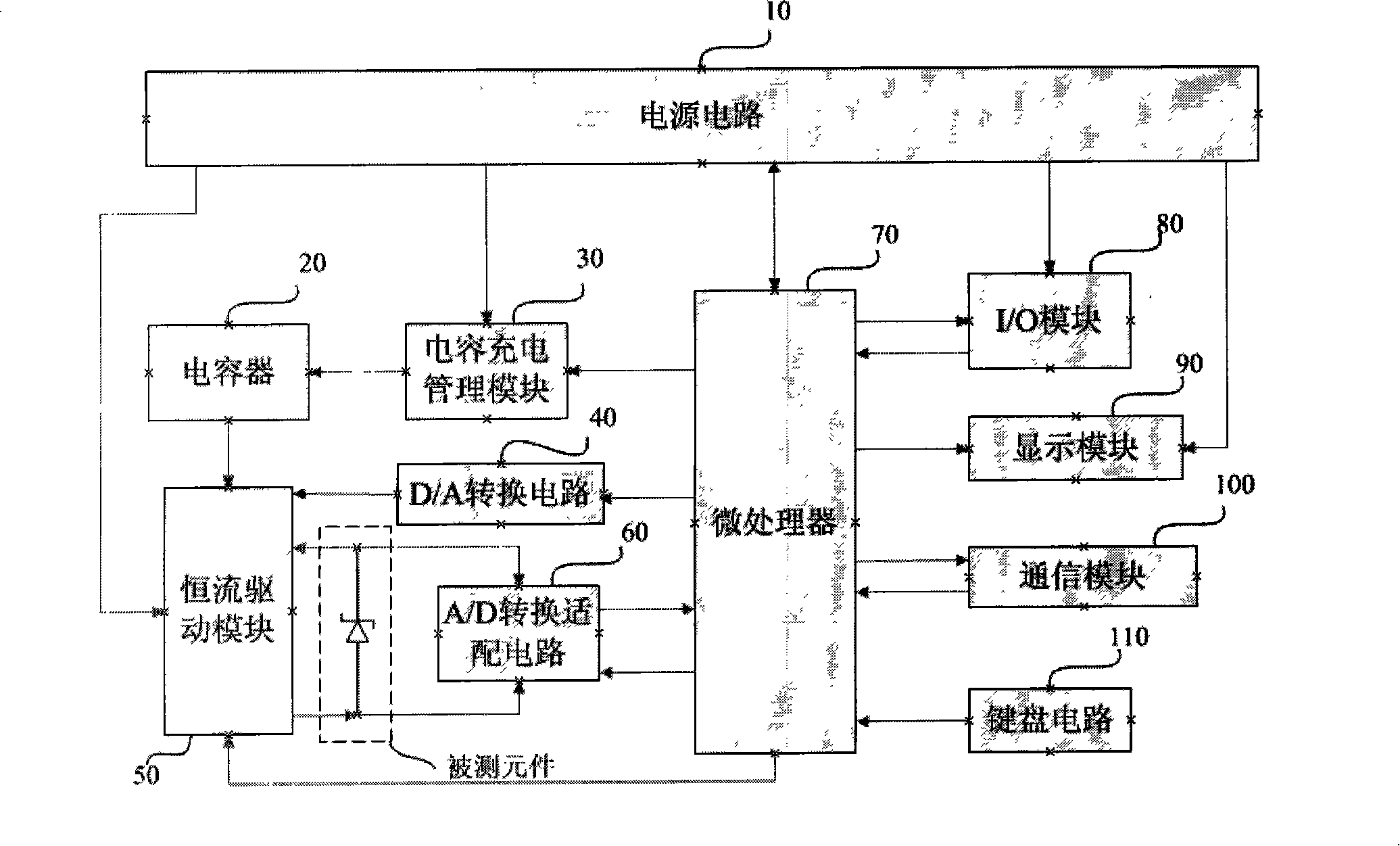
[0033] refer to figure 1 , a diode electrical characteristic test system, comprising:

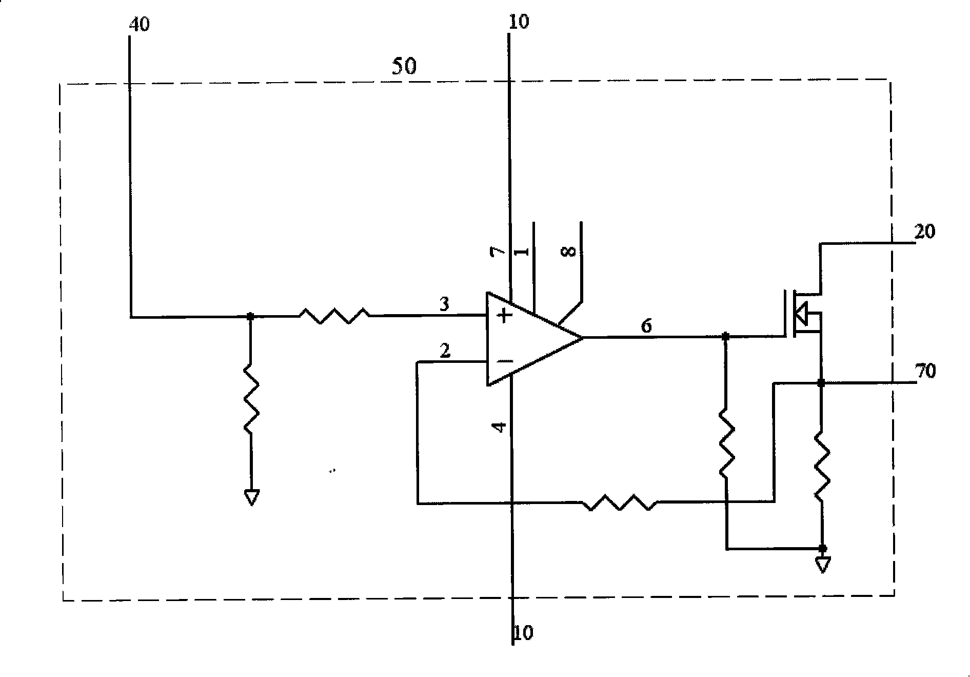
[0034] A constant current drive module 50, used to generate a stable current to the diode under test;

[0035] A D / A conversion circuit 40, connected to the constant current drive module, used to set the control analog quantity of the constant current drive module;

[0036] A capacitor 20, connected to the constant current drive module, used to provide the constant current drive module with an instantaneous high current power supply;

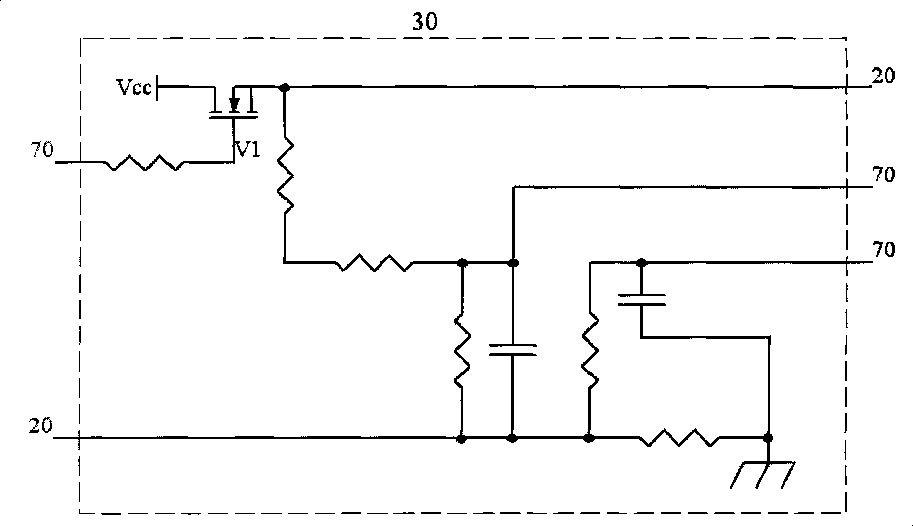
[0037] A capacitor charging management module 30, connected to the capacitor, used to manage the charging of the capacitor and detect the state of the capacitor;

[0038] An A / D conversion adaptation circuit 60, which is used to sample the voltage at both ends of the diode under test and ...


PUM


Abstract

The invention relates to a diode electrical property test system, which comprises: a constant current driving module for producing stable current for the tested diode; a D / A switching circuit for controlling the analog quantity of the given constant current driving module; a capacitor for providing a power supply of transient heavy current for the constant current driving module; a capacitor charging management module for managing the charging of the capacitor and detecting the state of the capacitor; an A / D conversion adaptation circuit for sampling the voltage of both ends of the tested diode and converting the voltage into the digital quantity which is transmitted to a microprocessor; the microprocessor; an I / O module; a keyboard circuit; a communication module; a display module; and apower supply circuit. The diode electrical property test system of the invention has advantages of low energy consumption, large output amplitude, free setup of testing parameters, high testing accuracy and fast testing speed.

Description

(1) Technical field [0001] The invention relates to a diode electric characteristic testing system. (2) Background technology [0002] The diode electrical characteristic test system is used for the analysis and control of diode product quality and the identification of product indicators: parameters such as transient thermal resistance ΔVF, reverse transient thermal resistance ΔVFR, breakdown voltage VBR1-VBR4, forward voltage drop VFm and VF , Leakage current Ir, dynamic resistance Rdz. The existing diode electrical characteristic test system mainly has the following disadvantages: [0003] 1. The accuracy is difficult to characterize the product positioning: for example, the heating current of the transient thermal resistance ΔVF is 100A, the general error of the user's reading is about 6-10mV, and the accuracy index is ±2mV, that is to say, the absolute difference is used in the 4mV production line Due to the temperature rise of the internal components, the error is ev...

Claims


Application Information

Patent Timeline
Patent Type & Authority Patents(China)
IPC IPC(8): G01R31/26
Inventor 周道明郑国军
Owner 金天
Learn More