Strong push type detaching mechanism of car clutch

A separation mechanism and clutch technology, applied in the direction of clutches, mechanical drive clutches, mechanical equipment, etc., can solve problems such as separation mechanism failure, and achieve the effects of improving separation efficiency, increasing service life, and improving strength and rigidity

Inactive Publication Date: 2008-11-05
QIJIANG GEAR TRANSMISSION
View PDF0 Cites 3 Cited by
  • Summary
  • Abstract
  • Description
  • Claims
  • Application Information

AI Technical Summary

Problems solved by technology

[0004] The purpose of this utility model is to provide a kind of powerful push-type separation mechanism of the automobile clutch in view of the above-mentioned deficiencies in the prior art. It adopts the structure of the separation push arm to solve the problem of early failure of the separation mechanism and ensure the parallel sliding of the separation bearing. and can improve the separation force

Method used


Image

  • Strong push type detaching mechanism of car clutch
  • Strong push type detaching mechanism of car clutch

Examples


Embodiment Construction

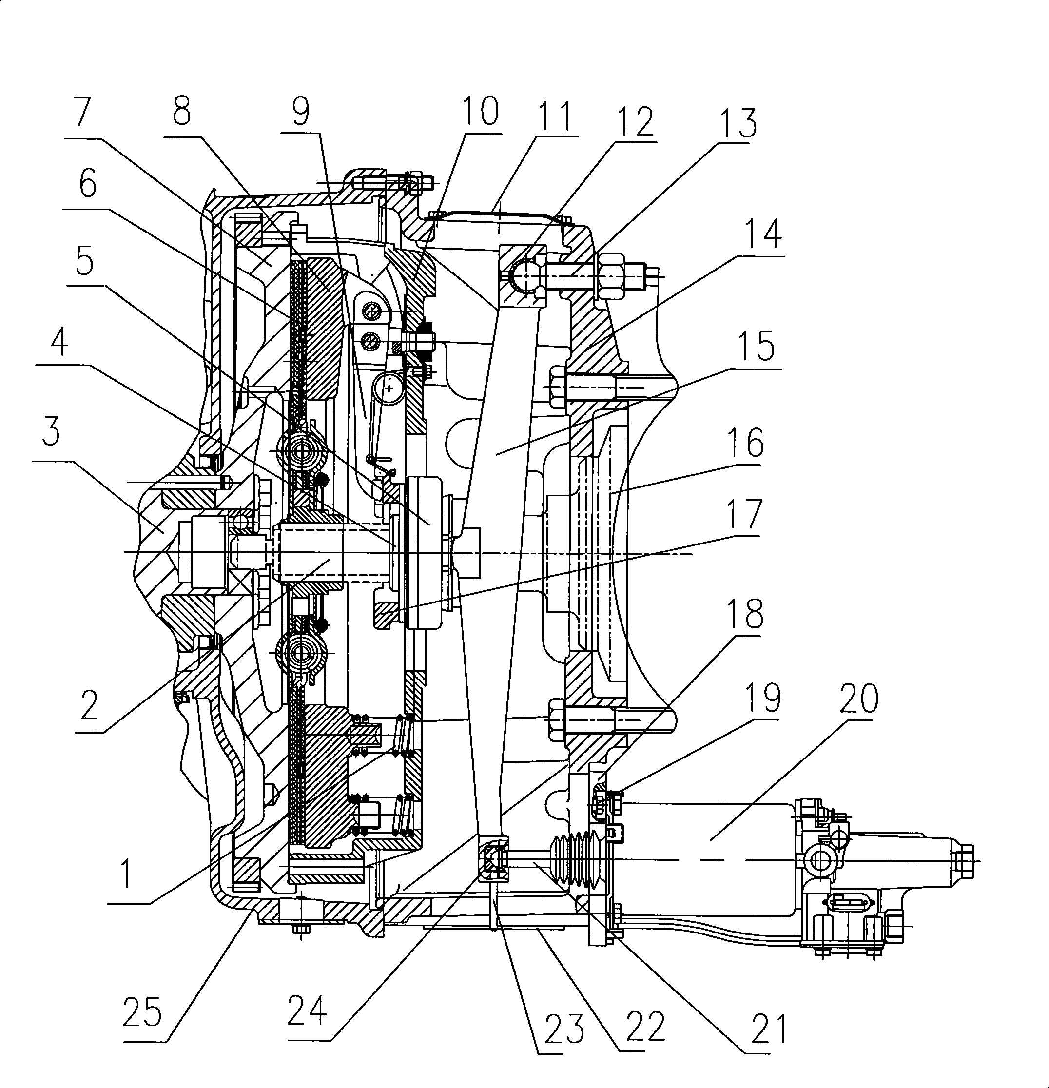
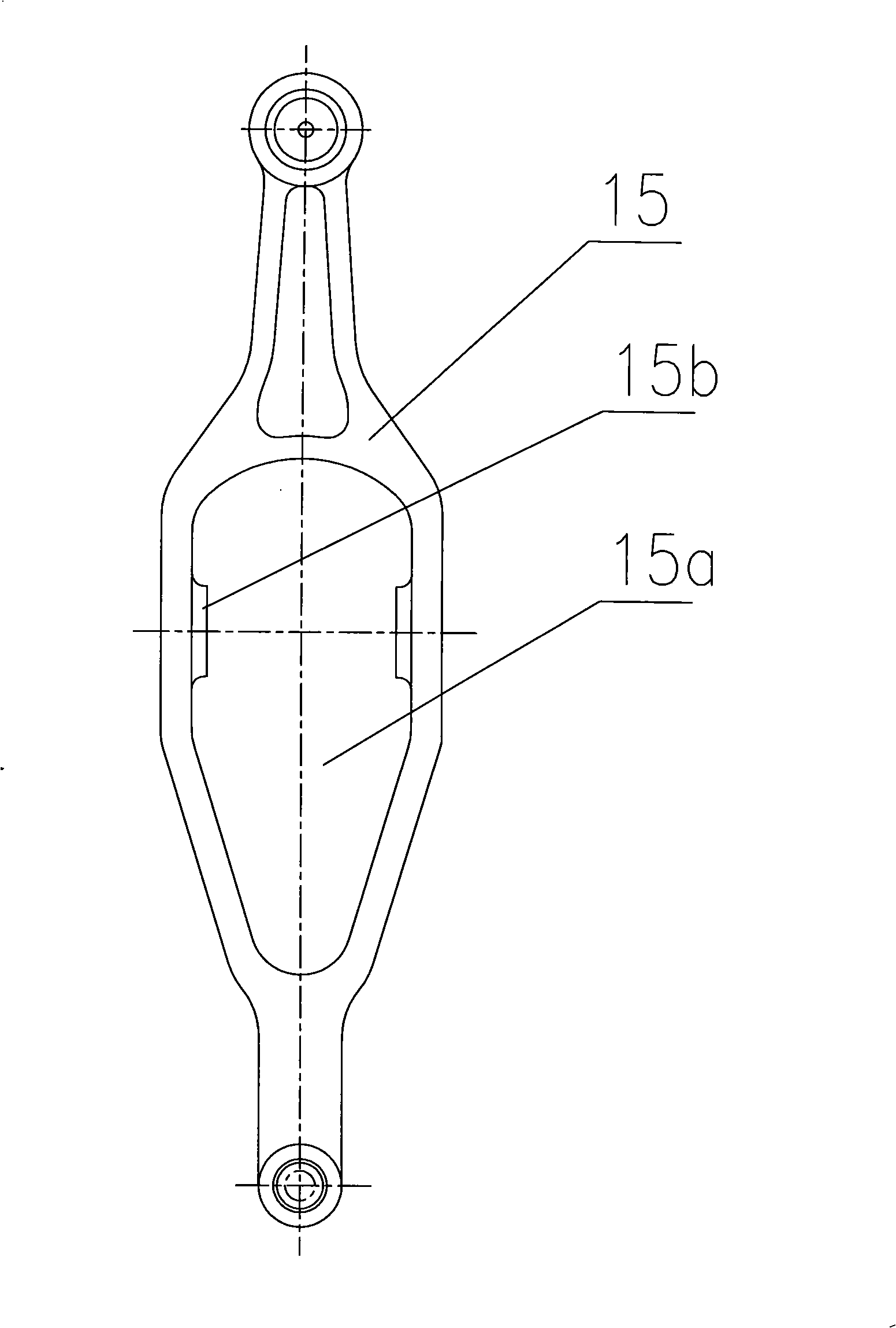
[0012] see figure 1 , figure 2 , a kind of embodiment of the strong push type separation mechanism of automobile clutch of the present invention. A disengagement push arm 15 is arranged inside the clutch housing 14 . The disengagement push arm 15 has a structure in which the middle part is wider than both ends, and the middle part is provided with a hole 15 a for making way. The hole 15a for giving way is a flat hole, the length of the flat hole extends along the arm length direction of the separation push arm, the width of the flat hole extends along the arm width direction of the separation push arm, and the flat hole can be set as a rectangular hole, or An oval hole, or a hole in a shape that is wider on one side than the other. The middle part of the separation push arm 15 is located on both sides of the hole 15 for giving way, and is provided with a protrusion 15b in contact with the end surface of the release bearing 5. The protrusion 15b is symmetrically arranged on ...


PUM


Abstract

The invention discloses a strength push-type separation mechanism of an automobile clutch, comprising a clutch shell, a front-end cover shaft sleeve, a release bearing, a separating ring, and a booster pump controlled by a control pedal. A separating pushing arm is arranged in the clutch shell. The pivot side of the separating pushing arm is articulated with an articulated component fixed on the clutch shell. The effort side of the separating pushing arm is articulated with a projecting shaft end of the booster pump. The middle part of the separating pushing arm is provided with a hole used for abdicating. The front-end cover shaft sleeve passes from the hole to sliding coordinate with the release bearing and the separating ring. The middle part of the separating pushing arm on both sides of the hole used for abdicating is provided with a salient contacted with the release bearing head face. The separating ring is connected with a separating claw of the clutch. The invention adopts a separating pushing arm structure to solve a problem of the separation mechanism early failure and guarantee the release bearing slides in parallel, and can improve separating force.

Description

technical field [0001] The invention relates to a separation mechanism of a clutch, in particular to a powerful push type separation mechanism of an automobile clutch. Background technique [0002] The automobile clutch and clutch separation mechanism are located in the flywheel housing between the engine and the transmission, and are the connection assembly between the engine and the transmission system. Its main function is to transmit or cut off the power from the engine to ensure the car starts smoothly, to ensure the smooth shifting of the transmission system, to reduce the meshing impact of the gear pair during the shifting process, and to prevent the overload of the transmission system at the same time, and to play the role of overload protection. The failure of the vehicle will directly lead to the failure of the normal operation of the car. Usually, the structure of the clutch separation mechanism of a truck or a large passenger car includes: a separation fork, a s...

Claims


Application Information

Patent Timeline
Patent Type & Authority Applications(China)
IPC IPC(8): F16D23/14
Inventor 李庆谭荣
Owner QIJIANG GEAR TRANSMISSION
Why Eureka
Try Eureka