Tube joint

A technology of pipe joints and inner joints, applied in the field of pipe joints, can solve problems such as difficult disassembly, and achieve the effect of safe and easy disassembly operations

Active Publication Date: 2011-05-18
DISCO CORP
View PDF1 Cites 0 Cited by
  • Summary
  • Abstract
  • Description
  • Claims
  • Application Information

AI Technical Summary

Problems solved by technology

Therefore, there is a problem that disassembly work is difficult

Method used


Image

  • Tube joint
  • Tube joint
  • Tube joint

Examples


Embodiment Construction

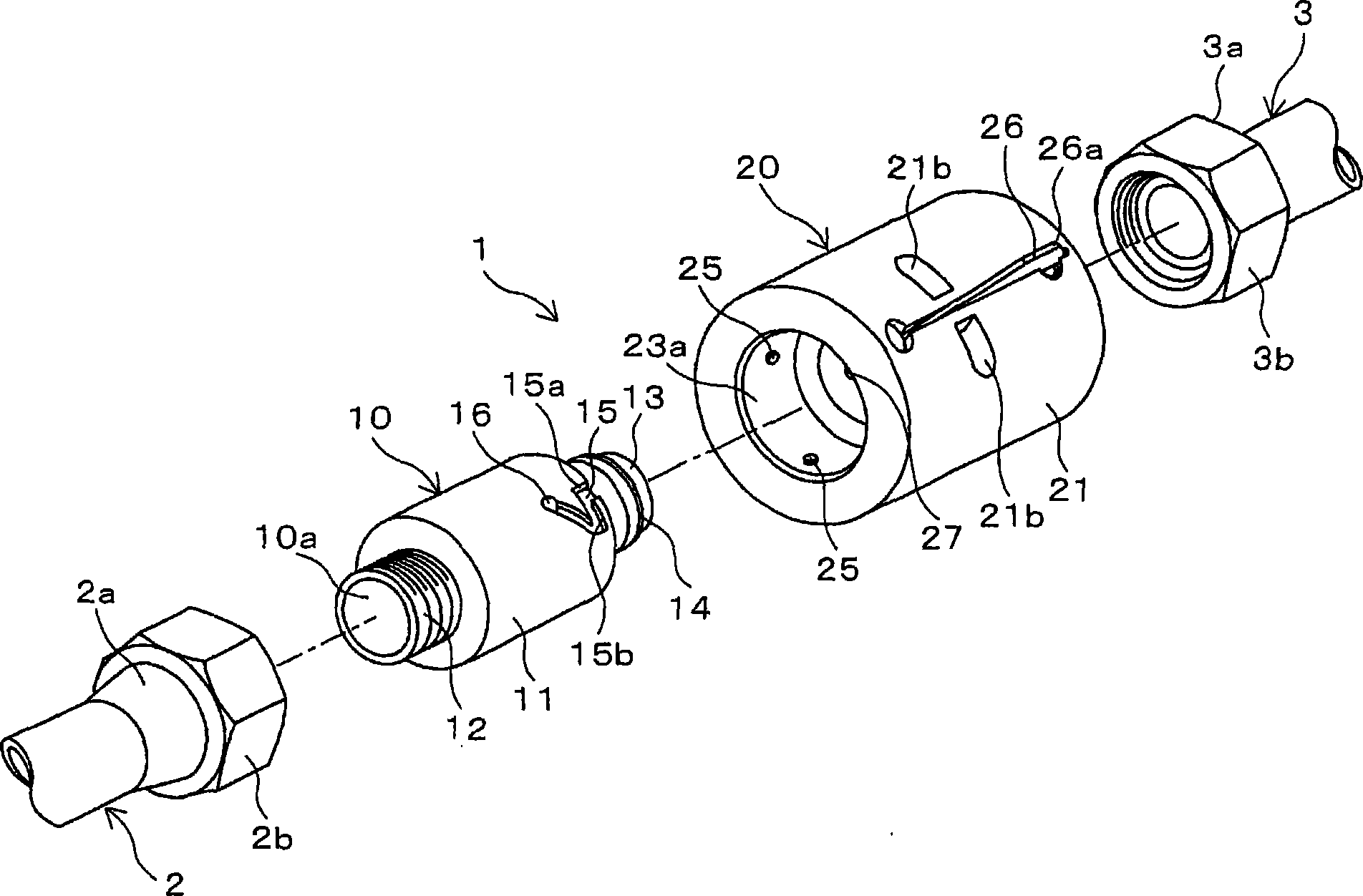
[0024] figure 1 It is a perspective view showing each member and pipe bodies 2 and 3 constituting the pipe joint 1 according to one embodiment. The pipe joint 1 is composed of a cylindrical inner joint 10 and a socket 20 . The inner joint 10 and the sleeve 20 of the pipe joint 1 are mounted on the front ends of the respective pipe bodies 2, 3 to detachably connect the pipe bodies 2, 3.

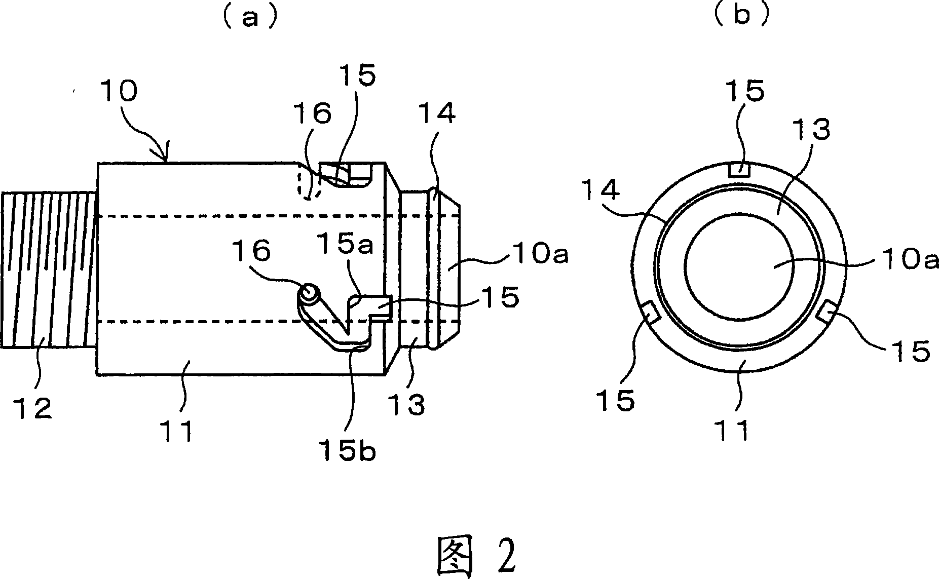
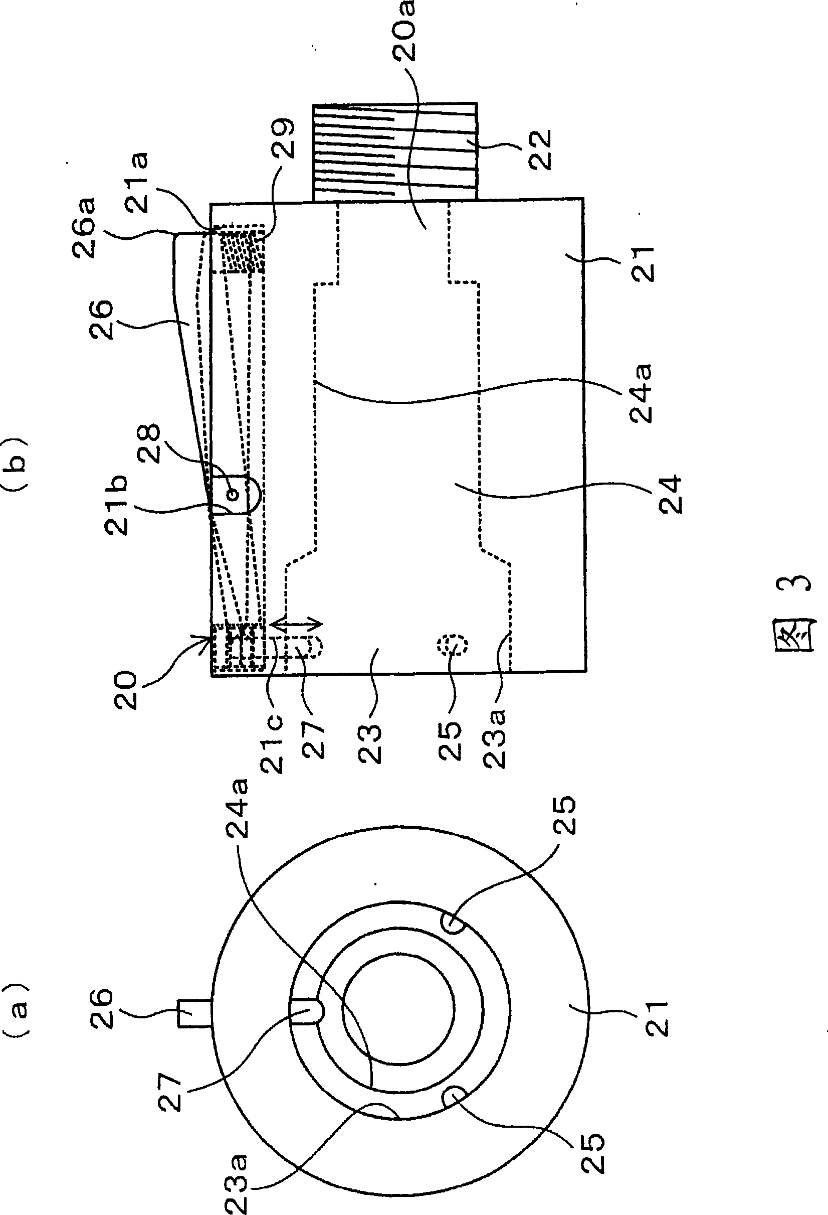
[0025] Connectors 2a, 3a integrally formed with nuts 2b, 3b are attached to the front ends of the pipe bodies 2, 3, respectively. The nipple 10 has a cylindrical large-diameter cylindrical portion 11 serving as a base, and a cylindrical thread portion 12 is coaxially formed at one axial end portion of the large-diameter cylindrical portion 11 . Further, the socket 20 has a cylindrical main body 21 serving as a base, and a cylindrical threaded portion 22 is coaxially formed at one axial end of the main body 21 (see FIG. 3 ). By screwing the nuts 2b, 3b of the couplings 2a, 3a on the threaded...


PUM


Abstract

The invention provides a pipe joint, which prevents a pair of joint components from separating fiercely due to the pressure in the piping when disassembled, and is operated safely and easily. The pipe joint (1) is composed of an internal joint (10) and a pipe sleeve (20). A pin blocking slot (15) is formed on the periphery surface of the major diameter columnar part (11) of the internal joint (10), so that a fixed pin (25) and a movable pin (27) provided on the internal circumference (23a) of the internal joint inserting hole (23) of the pipe sleeve (20) are blocked in the pin blocking slot (15), the internal joint (10) is inserted in the pipe sleeve (20) along the pin blocking slot (15) at the same time, and the movable pin (27) matches with a matching concave part (16) to form a mounting state. When disassembled, each pin (25, 27) is hooked on the second bending part (15b) in the middle of each pin blocking slot (15), to prevent the internal joint (10) and the pipe sleeve (20) from separating fiercely, and the internal pressure in the piping is released.

Description

technical field [0001] The present invention relates to a pipe joint mounted on the front end of a pair of connected pipe bodies to detachably connect these pipe bodies. Background technique [0002] In a wet cutting device using a diamond blade for slicing semiconductors and electronic components, etc., processing is performed while supplying cutting water to the processing point in order to suppress heat generation at the processing point and remove chips generated when cutting semiconductors and the like. Cutting water becomes waste water after its use is terminated, and the waste water is collected in waste water treatment facilities through piping for treatment. This waste water treatment facility generally has a pump that sucks waste water and a filter that filters cuttings and the like. [0003] Since the above-mentioned cuttings and the like are trapped in the filter used in the waste water treatment facility, there is a possibility that the clogging of the mesh wil...

Claims


Application Information

Patent Timeline
Patent Type & Authority Patents(China)
IPC IPC(8): F16L37/248F16B21/12F16L21/00
Inventor 吉田干风吕中武
Owner DISCO CORP
Why Eureka
Try Eureka