Thermo-acoustic engine system using temperature-variable heat source
A thermoacoustic engine, heat source technology, applied in Stirling engines, machines/engines, mechanisms that generate mechanical power, etc., can solve problems such as the inability to fully utilize heat effectively, and achieve the effect of improving conversion efficiency
- Summary
- Abstract
- Description
- Claims
- Application Information
AI Technical Summary
Problems solved by technology
Method used
Image
Examples
Embodiment 1
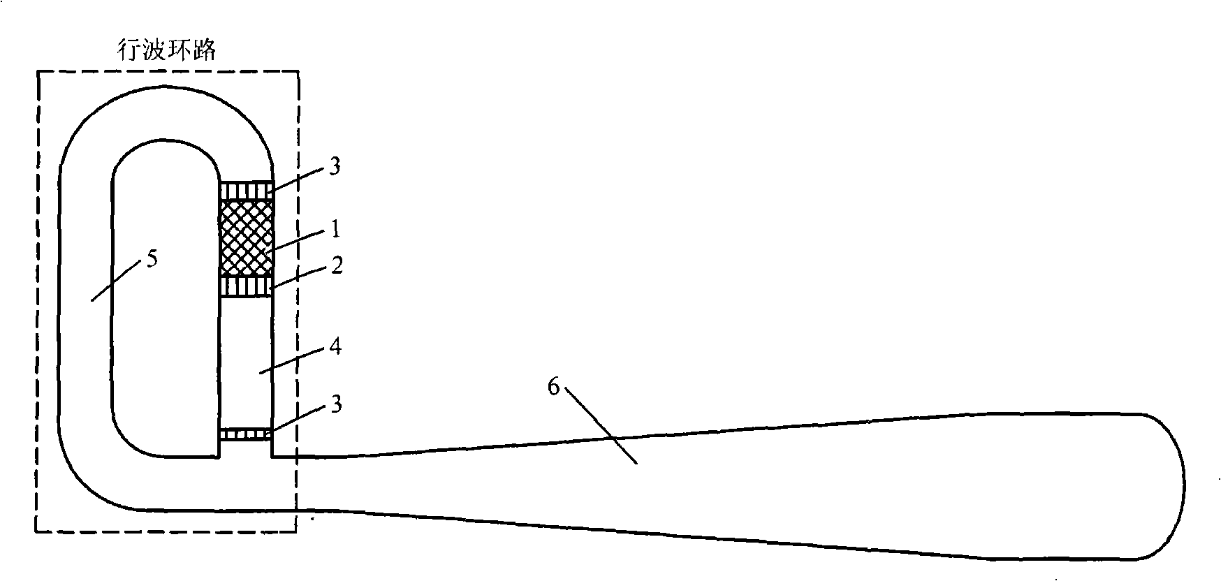
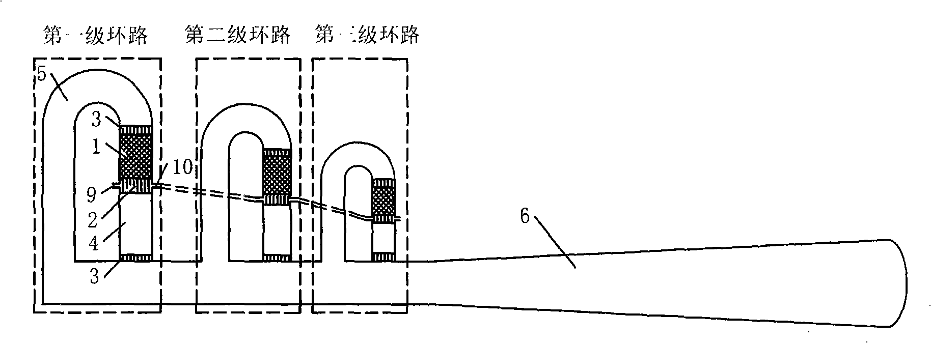
[0047] Such as figure 2 As shown, as an example, three traveling wave loops are connected on the resonant tube of the thermoacoustic engine system. Taking the first traveling wave loop on the left as shown in the figure as an example, the design structure of each traveling wave loop is as follows: starting from the resonance tube 6, connect the feedback tube 5, the low-temperature inverter Heater 3 (such as adopting room temperature heat exchanger 3 for heat exchange with room temperature), regenerator 1, high temperature heat exchanger 2, thermal buffer tube 4, the other end of thermal buffer tube 4 is for example passed through another same low temperature exchanger. Heater 3 is connected with resonant tube 6 . Each high-temperature heat exchanger has an input port 9 and an output port 10 for the input and output of the heat-carrying fluid medium, and the high-temperature heat exchanger output port 10 of the first-stage traveling wave loop is connected to the second-stage ...
Embodiment 2
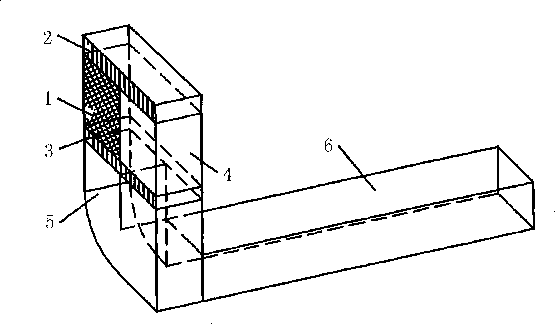
[0049] figure 1 The single-stage traveling wave thermoacoustic engine in can also be designed as image 3 structure shown. exist image 3 Among them, the regenerator 1, the thermal buffer tube 4, the feedback tube 5 and the resonance tube 6 adopt a square structure, and the regenerator 1 and the thermal buffer tube 4 are arranged between the high-temperature heat exchanger 2 and the low-temperature heat exchanger 3, The regenerator 1 and the thermal buffer pipe 4 are separated by a partition, which extends through the low temperature heat exchanger 3 and serves as the inner side wall of the feedback pipe 5 on the outside of the low temperature heat exchanger 3, and the feedback pipe 5 The outer sidewall is formed by the integral shell forming the traveling wave loop. Such as Figure 4 As shown, in order to make the structure of multiple traveling wave loops more compact, the partitions of the multistage traveling wave loops are connected into a whole. A single loop uses ...
Embodiment 3
[0051] Such as Figure 5 As shown, the regenerator 1, high-temperature heat exchanger 2, thermal buffer pipe 4, feedback pipe 5 and shared low-temperature heat exchanger of each stage in this embodiment adopt a square structure, but it is different from Embodiment 2 The most important thing is that the regenerator and thermal buffer tube of the previous stage are not close to each other but separated from each other and form a certain space with the high-temperature heat exchanger and the shared low-temperature heat exchanger, in which the high-temperature heat exchange of the latter stage is accommodated. Regenerators, regenerators and thermal buffer tubes, regenerators and thermal buffer tubes at all levels are close together and share the same low-temperature heat exchanger 3, and the loop of the latter stage is wrapped in the loop of the previous stage Inside, the regenerators of each stage are separated by a partition, and a part of the partition extends into the resonant...
PUM
 Abstract
Description
Claims
Application Information
 - R&D
- Intellectual Property
- Life Sciences
- Materials
- Tech Scout
- Unparalleled Data Quality
- Higher Quality Content
- 60% Fewer Hallucinations
Browse by: Latest US Patents, China's latest patents, Technical Efficacy Thesaurus, Application Domain, Technology Topic, Popular Technical Reports.
© 2025 PatSnap. All rights reserved.Legal|Privacy policy|Modern Slavery Act Transparency Statement|Sitemap|About US| Contact US: help@patsnap.com


