Magnetic disk drive and soldering method of feed-through
A technology for disk drives and magnetic disks, used in instruments, poor vibration/sound insulation/absorption, sealing gaskets, etc., can solve problems such as poor sealing ability, large diffusion coefficient, and small helium gas, and achieve improved leakage service life, reliable Solder bonding, the effect of preventing deterioration
- Summary
- Abstract
- Description
- Claims
- Application Information
AI Technical Summary
Problems solved by technology
Method used
Image
Examples
Embodiment 1
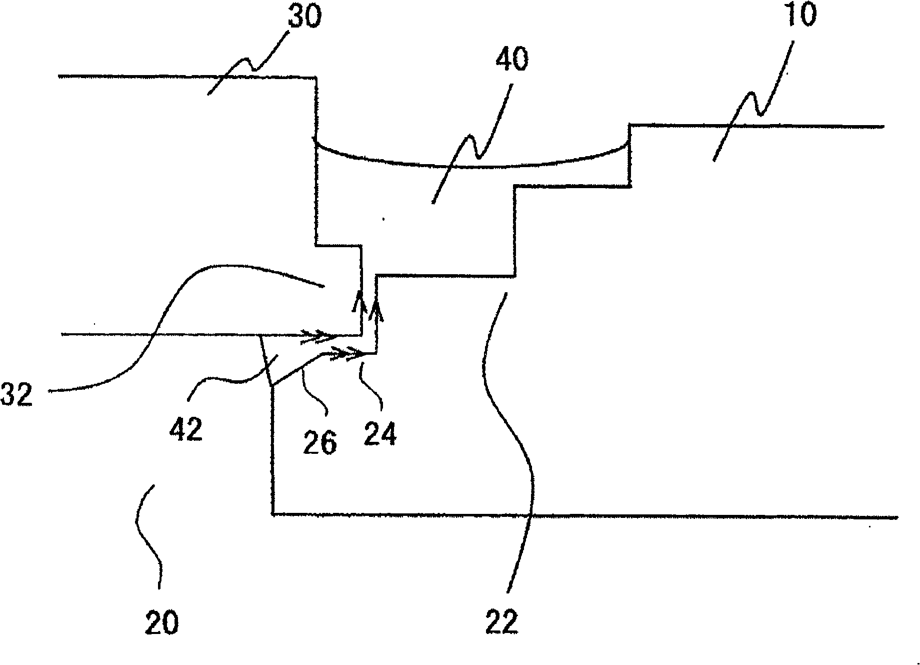
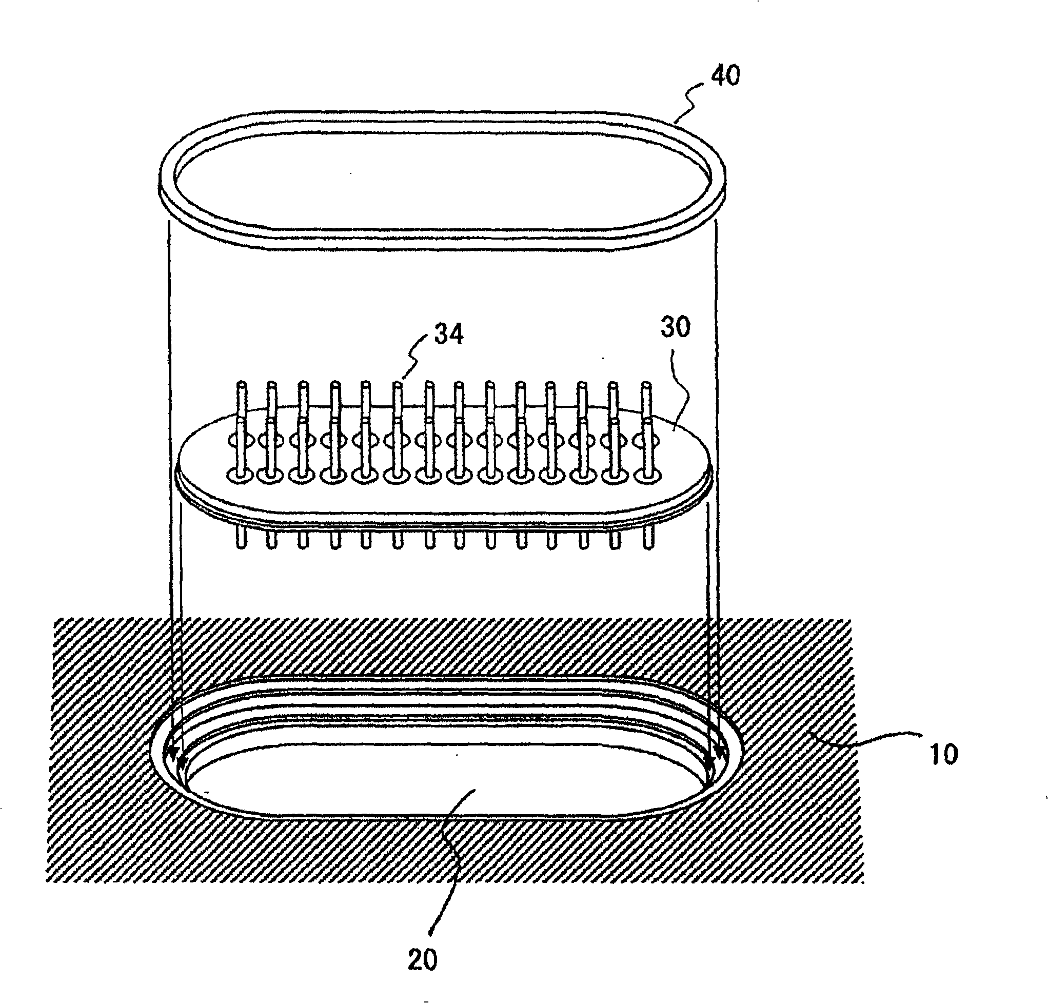
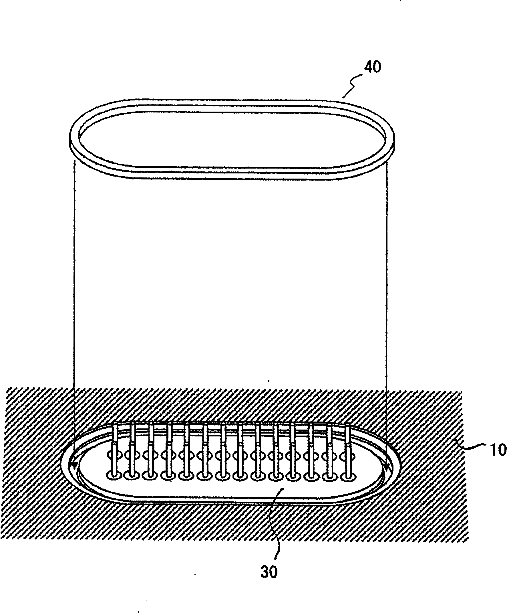
[0055] refer to figure 1 and figure 2 to describe the structure of the base. figure 1 A cross-sectional view of the joint portion between the base and the lead is shown. figure 2 The relationship between the periphery of the opening showing the base, the leads, and the solder prior to bonding is shown. An opening 20 for mounting the lead wire 30 is provided at the bottom of the base 10 , and a stepped portion 22 is provided inside the periphery forming the opening 20 . The stepped portion 22 is composed of three-level stepped surfaces, wherein a stepped surface 24 facing the opening 20 has an edge opposite to the opening 20, and a flange 32 of the lead wire 30 is placed on the stepped surface 24, and has The ramp 26 extends to the outside of the base 10 .
[0056] Next, refer to Figures 1 to 4 A description will be made of a process of manufacturing a hermetically sealed magnetic disk drive in which the base 10 is bonded to the leads 30 by welding to seal the low-den...
Embodiment 2
[0072] Figure 6 A cross-section of the joint portion between the base and the leads of the sealed magnetic disk drive according to Embodiment 2 is shown. The base 10 corresponds to the 90° product base in Embodiment 1. Leads 30 include as Figure 6(a) A lead shown in which a bump 35 having a width of 0.2 mm and a height of 0.3 mm is formed on the surface edge of the flange portion not requiring solder wetting, and includes such as Figure 6 (b) A lead shown in which a groove 36 having a width of 0.2 mm and a depth of 0.3 mm is formed on its edge.
[0073] As in Embodiment 1, two solder pressing pieces 40 are used, each of which is composed of Sn-3Ag-0.5Cu (mass percentage), has a width of 1.0 mm and a thickness of 1.0 mm, and is elliptical shape. According to the same procedure as in Embodiment 1, the base 10 and the lead 30 were bonded by soldering. Then, as in Embodiment 1, the components of the disk drive are mounted on the base 10, and then the base and the seal are ...
Embodiment 3
[0079] Figure 7 A section of a joint portion between a base and leads of a sealed magnetic disk drive according to Embodiment 3 is shown. The base 10 corresponds to the 90° product base in Embodiment 1. In the leads 30 , portions that do not require solder wetting are covered with a solder resist 37 , or a masking tape 38 is attached.
[0080] As in Embodiment 1, two solder pressing pieces 40 are used, each of which is composed of Sn-3Ag-0.5Cu (mass percentage), has a width of 1.0 mm and a thickness of 1.0 mm, and is elliptical shape. According to the same procedure as in Embodiment 1, the base 10 and the lead 30 were bonded by soldering. Then, as in Embodiment 1, the components of the disk drive are mounted on the base 10, and then the base and the seal are joined, so that the low-density gas is sealed in the housing.
[0081] In order to evaluate the lifetime of the low density gas seal for each sealed disk drive, a temperature cycling test as in Example 1 was performed...
PUM
| Property | Measurement | Unit |
|---|---|---|
| width | aaaaa | aaaaa |
Abstract
Description
Claims
Application Information
 - R&D
- Intellectual Property
- Life Sciences
- Materials
- Tech Scout
- Unparalleled Data Quality
- Higher Quality Content
- 60% Fewer Hallucinations
Browse by: Latest US Patents, China's latest patents, Technical Efficacy Thesaurus, Application Domain, Technology Topic, Popular Technical Reports.
© 2025 PatSnap. All rights reserved.Legal|Privacy policy|Modern Slavery Act Transparency Statement|Sitemap|About US| Contact US: help@patsnap.com


