Angle-adjustable pipeline connecting structure, installing method and long-line pipeline

A connection structure and angle adjustment technology, applied in the direction of adjustable connection, pipe/pipe joint/pipe fitting, passing element, etc., can solve problems such as pipe angle steering, avoid liquid leakage and save time and cost.

Pending Publication Date: 2019-05-21
蓝钿(北京)流体控制设备有限公司
View PDF0 Cites 0 Cited by
  • Summary
  • Abstract
  • Description
  • Claims
  • Application Information

AI Technical Summary

Problems solved by technology

[0004] In order to solve the above problems, the present invention discloses an angle-adjustable pipe connection structure, which can make the connection of long-line pipes suitable for high-pressure working conditions, and the present invention can solve the problem of pipe angle turning

Method used


Image

  • Angle-adjustable pipeline connecting structure, installing method and long-line pipeline
  • Angle-adjustable pipeline connecting structure, installing method and long-line pipeline
  • Angle-adjustable pipeline connecting structure, installing method and long-line pipeline

Examples


Embodiment 1

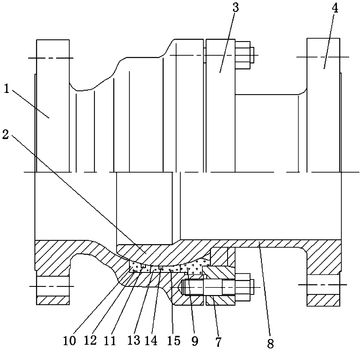
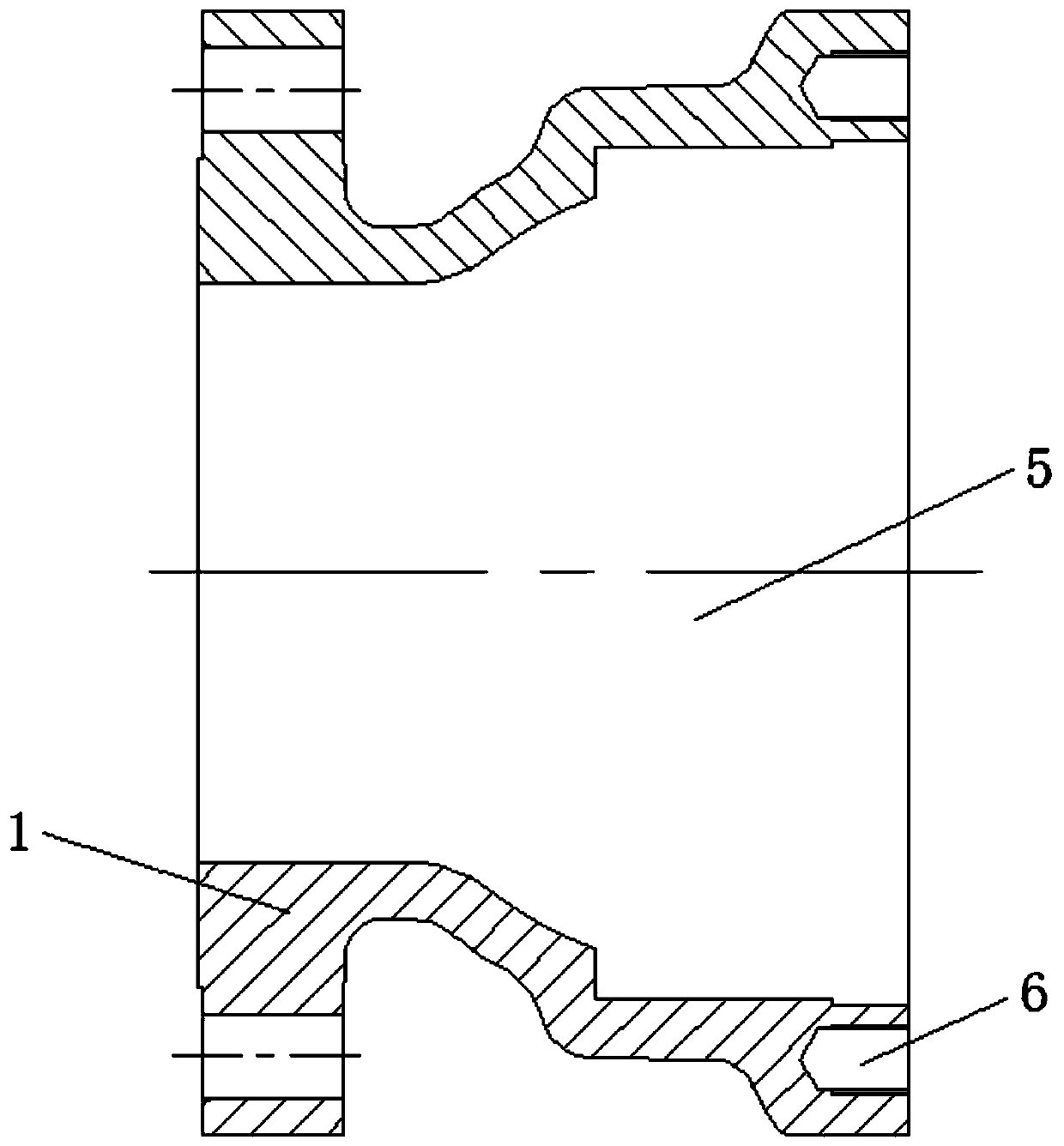
[0040] Such as Figure 1~2 As shown, an angle-adjustable pipeline connection structure includes a valve body 1, a valve ball 2, a first flange 3 and a second flange 4; one end of the valve body 1 is provided with a connecting cavity 5, the The end is provided with an interface with a small inner side and a large outer side; the valve body 1 is also provided with a first connecting portion 6; the first flange 3 is provided with a second connecting portion 7; the second connecting portion 7 is connected to the The first connecting part 6 is connected; the valve ball 2 is located inside the connecting cavity 5; the second flange 4 passes through the first flange 3 through the water supply pipe 8 to connect the interface with the valve ball 2 .

[0041] The present invention realizes the rotation of the water supply pipeline 8 through the setting of the valve ball 2, and the interface is set to be small on the inside and large on the outside, so that when the pipeline rotates, it ...

Embodiment 2

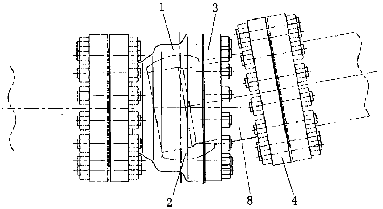
[0048] Such as image 3 As shown, a long-line pipeline has an angle-adjustable pipeline connection structure.

[0049] By using the above-mentioned angle-adjustable pipeline connection structure to connect long-line pipelines, the problems of misalignment correction and steering during the pipeline connection process can be greatly solved, making pipeline connection more flexible and providing more convenience for pipeline construction; On this basis, the long-line pipeline also has good sealing and wear resistance, and can work in high-pressure medium conditions.

[0050] In this embodiment, the size of the interface connecting the inner cavity 5 can make the valve body 1 rotate 0-10° in the connecting inner cavity 5, so as to achieve a maximum selection angle of 20°. In this embodiment, the specific connection structure The installation steps are as follows:

[0051] (a) Install the sealing ring at the corresponding positions of the retaining ring 10 and the packing ring 1...


PUM


Abstract

The invention belongs to the field of sludge treatment equipment, and discloses an angle-adjustable pipeline connecting structure. The angle-adjustable pipeline connecting structure comprises a valvebody, a valve ball, a first flange and a second flange; the inner side of one end of the valve body is provided with a connecting inner cavity, and the end is provided with a port with the small innerside and the large outer side; the valve body is further provided with a first connecting portion; the first flange is provided with a second connecting portion; the second connecting portion is connected with the first connecting portion through a fixing part; the valve ball is located in the connecting inner cavity; and the second flange penetrates through the first flange and the port througha water supply pipeline to be connected with the valve ball. The invention further discloses an installing method of the pipeline connecting structure and a long-line pipeline with the pipeline connecting structure. Therefore, connection of the long-line pipeline can be applied to the high-pressure work condition, and the pipeline angle steering problem can be solved.

Description

technical field [0001] The invention belongs to the field of sludge treatment equipment, and in particular relates to an angle-adjustable pipeline connection structure and installation method, and a long-line pipeline. Background technique [0002] Most of the existing adjustable pipeline connection technologies are metal hose connections or pipeline telescopic connections, among which metal hose connections cannot be used in high-pressure working conditions, and pipeline telescopic connections cannot solve the problem of pipeline angle steering. [0003] During the construction of long-line pipelines, the two ends of the pipeline are generally constructed at the same time and connected in the middle. However, due to factors such as the environment or personnel, the connecting part will be inclined, which will easily cause seal leakage, and in severe cases will cause unnecessary production accidents. . Contents of the invention [0004] In order to solve the above problem...

Claims


Application Information

Patent Timeline
Patent Type & Authority Applications(China)
IPC IPC(8): F16L27/04F16L27/053
Inventor 裘铮浩顾赛杰
Owner 蓝钿(北京)流体控制设备有限公司
Why Eureka
Try Eureka