
Fuel cell and its fabrication method

A fuel cell and electrolyte technology, which is applied in the direction of fuel cells, fuel cell additives, fuel cell components, etc., can solve problems such as the difficulty of strengthening the frame to be bonded to electrodes, and achieve suppression of inhomogeneity, deformation, and composition changes Effect

Inactive Publication Date: 2008-10-08
TOYOTA JIDOSHA KK
View PDF1 Cites 2 Cited by
  • Summary
  • Abstract
  • Description
  • Claims
  • Application Information

AI Technical Summary

Problems solved by technology

However, it is difficult to bond a reinforced frame with gas channels to the electrodes

Method used


Image

  • Fuel cell and its fabrication method
  • Fuel cell and its fabrication method
  • Fuel cell and its fabrication method

Examples


no. 1 example

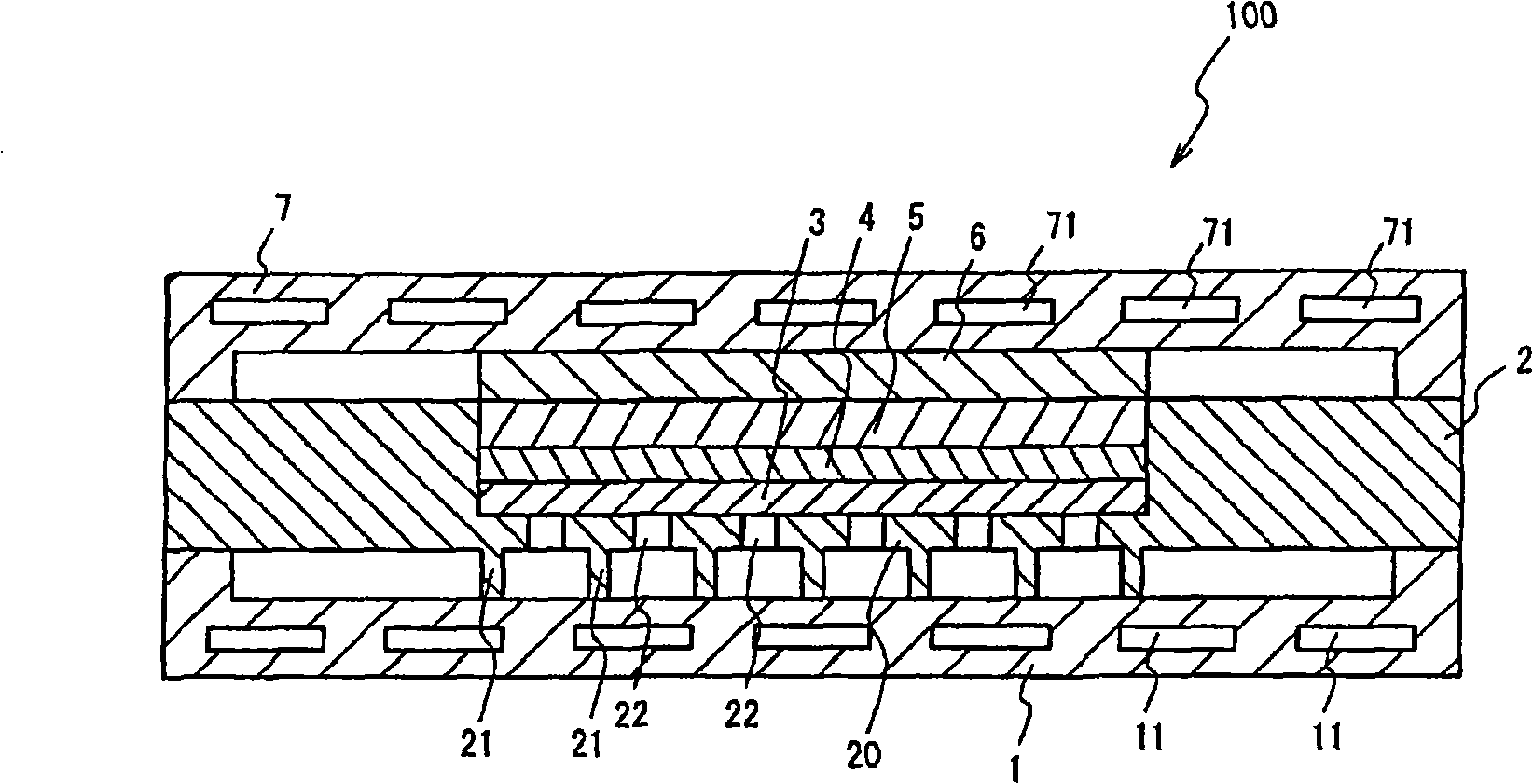
[0025] figure 1 A schematic cross-sectional view of a fuel cell 100 according to a first embodiment of the present invention is shown. In this embodiment, a hydrogen permeable membrane fuel cell is used as the fuel cell. Here, the hydrogen permeable membrane fuel cell has a hydrogen permeable membrane. The hydrogen permeable membrane is made of a hydrogen permeable metal. A hydrogen permeable membrane fuel cell has a structure in which an electrolyte having proton conductivity is provided on a hydrogen permeable membrane. A part of hydrogen supplied to the anode is converted into protons through a catalytic reaction. Protons are conducted in the electrolyte having proton conductivity, react with oxygen supplied to the cathode, and are converted into water. Electricity is generated from this. The structure of the fuel cell 100 will be described below.

[0026] Such as figure 1 As shown, the fuel cell 100 has separators 1 and 7 , a reinforcing frame 2 , a hydrogen permeab...


PUM

PropertyMeasurementUnit
thicknessaaaaaaaaaa

Abstract

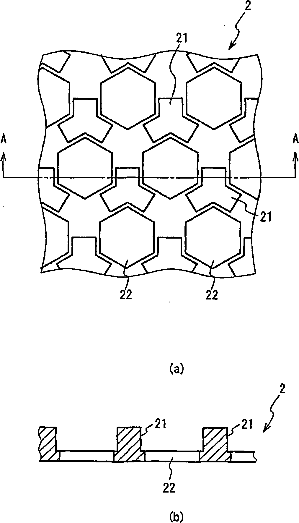
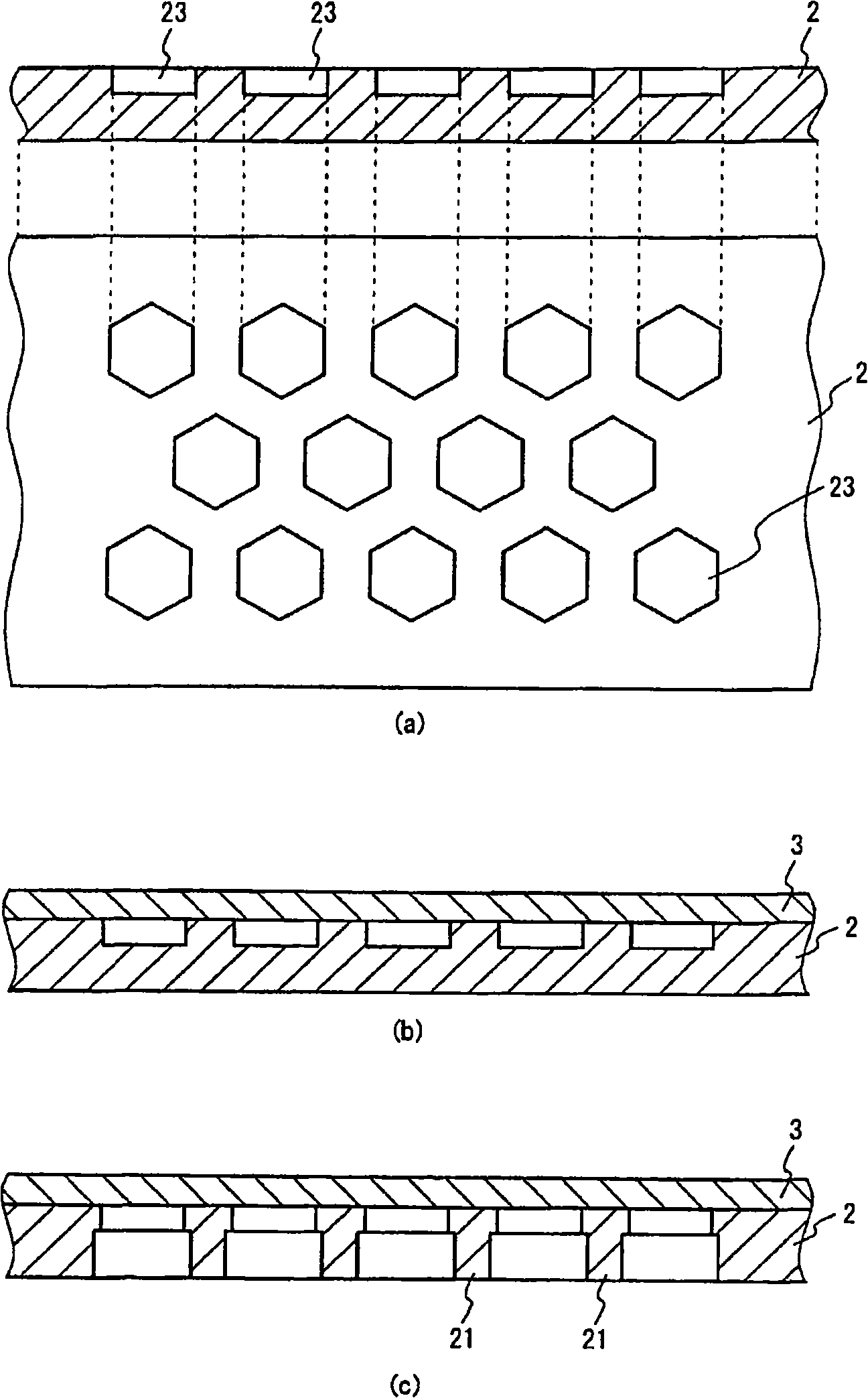
A method for fabricating a fuel cell (100) includes: a first step for forming at least one concave portion (23) on one side of a reinforcing frame (2) by half etching process; a second step for attaching a hydrogen separation film (3) onto one side of the reinforcing frame (2) by the clad method; and a third step for half-etching from a region corresponding to the concave portion (23) on the other side of the reinforcing frame (2) to the concave portion (23).

Description

technical field [0001] The present invention relates generally to fuel cells and methods of making fuel cells. Background technique [0002] In general, a fuel cell is a device that obtains electricity from fuels (hydrogen and oxygen). Because fuel cells are environmentally superior and can achieve high energy efficiency, fuel cells are being widely developed as energy supply devices. [0003] A fuel cell, for example, has a power generator in which electrodes hold an electrolyte. In order to reduce the thickness of the power generator structure, a reinforced frame that supports and strengthens the power generator is necessary. In this case, it is necessary to form gas passages such as through holes in the reinforcement frame in order to supply fuel gas to electrodes of the power generator. Also, it is necessary to join the reinforcement frame to the electrodes of the power generator in order to reinforce the power generator. However, it is difficult to bond a reinforced...

Claims


Application Information

Patent Timeline
Patent Type & Authority Applications(China)
IPC IPC(8): H01M8/02H01M8/12
CPCH01M8/0273H01M8/0247H01M8/0267H01M8/0297H01M8/04201H01M8/1226H01M8/1246H01M8/242H01M8/2425H01M2300/0071Y02E60/521Y02E60/525H01M8/0258Y02E60/50Y02P70/50
Inventor 伊泽康浩
Owner TOYOTA JIDOSHA KK
Learn More