
Relay

A relay and electromagnet technology, applied in the field of high-frequency relays, can solve the problems of low productivity, small degree of freedom, and difficulty in processing the movable iron piece 5, and achieve the effects of high productivity, low friction, and easy processing

Inactive Publication Date: 2012-03-28
ORMON CORP
View PDF2 Cites 0 Cited by
  • Summary
  • Abstract
  • Description
  • Claims
  • Application Information

AI Technical Summary

Problems solved by technology

[0006] However, in the above-mentioned high-frequency relay, if the groove portion 28 is to be formed on the movable iron piece 5 with a thick wall, it is necessary to perform press work or cutting work.
Therefore, the plate materials and processing methods that can be used are limited, and the degree of freedom in design is small
In addition, the processing of the movable iron piece 5 is not easy, and there is a problem of low productivity.

Method used


Image

  • Relay
  • Relay
  • Relay

Examples


Embodiment Construction

[0086] based on Figure 1 ~ Figure 2 3. A coaxial relay to which an embodiment of the present invention is applied will be described.

[0087] The coaxial relay of this embodiment is roughly constituted by a contact unit 10 , a movable iron piece 50 , an electromagnet unit 60 , a control unit 80 , and a cover 90 .

[0088] The contact unit 10 is composed of a base block 11 , a copper sheet 24 and a contact block 30 . Such as Figure 6 As shown, the base block 11 is a cuboid, and an escape groove 12 is formed in the center of the upper surface. In addition, around the escape groove 12 of the base block 11, a pair of positioning pins 16a, 16b protrude point-symmetrically, and threaded holes 17a, 17b are formed point-symmetrically. In order to ensure the directionality of assembly of the contact block 30, the positioning pins 16a, 16b and the threaded holes 17a, 17b are not arranged in line-symmetrical positions. In addition, through-holes 13 , 14 , and 15 for coaxial connect...


PUM


Abstract

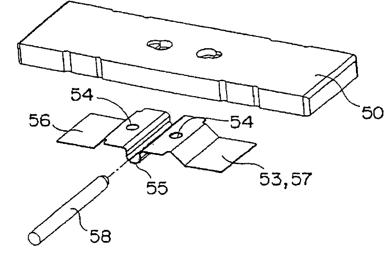
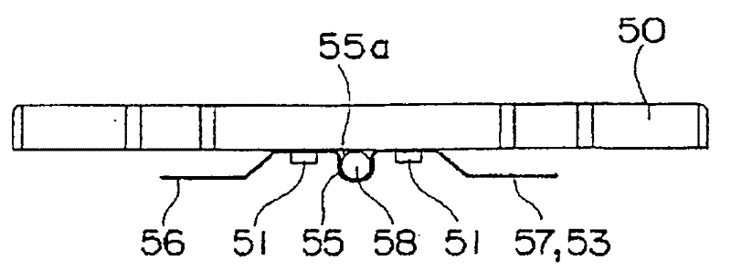
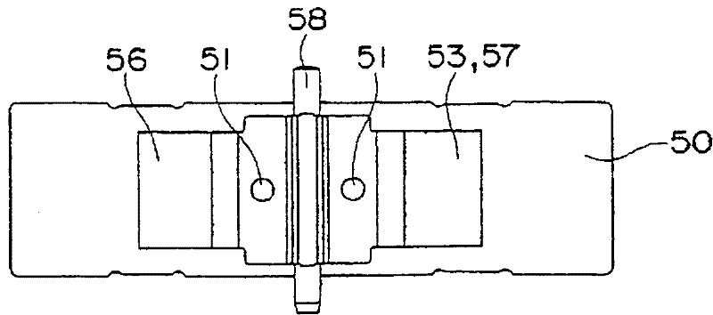
A relay having a large degree of freedom of design and a high productivity, wherein a support shaft (58) is inserted into a shaft hole formed by one face of a movable iron piece (50) and a plate spring (53) fixed to the one face of the movable iron piece (50), and the movable iron piece (50) is rotatably supported through the support shaft (58). Based on the magnetization and demagnetization of an electromagnet unit (60), the movable iron piece (50) is rotated about the support shaft (58) to alternately drive a contact unit (10) by both end parts of the plate spring (53). In particular, the support shaft (58) is inserted into the shaft hole formed by the flat one face of the movable iron piece (50) and a bearing part (55) formed by applying bending to the plate spring (53), and the movable iron piece (50) is rotatably supported thereon.

Description

technical field [0001] The present invention relates to relays, and in particular, to high-frequency relays used in playback equipment, measuring equipment, and the like. Background technique [0002] Conventionally, as a high-frequency relay, for example, based on the excitation and demagnetization of the electromagnet block 1, the contact block 2 is driven by the movable iron piece 5 rotating around the rotating shaft 27 to open and close the contacts (refer to Patent Document 1, 2). [0003] Patent Document 1: (Japanese) Unexamined Patent Publication No. 2003-257734 [0004] Patent Document 2: (Japanese) Unexamined Patent Publication No. 2003-272500 [0005] Among the above-mentioned high-frequency relays, for example, the Figure 4 As shown, a pair of protrusions 26, 26 are arranged side by side on one side of the thick movable iron piece 5 to form a groove portion 28, and a leaf spring 29 is screwed to the protrusion 26, thereby supporting the Axis of rotation 27 . ...

Claims


Application Information

Patent Timeline
Patent Type & Authority Patents(China)
IPC IPC(8): H01H50/18
CPCH01H51/2272H01H50/646H01H50/24
Inventor 太田章筱浦达生猿渡庸二郎中村正则
Owner ORMON CORP
Learn More