
Capacitance type gas sensor based on carbon nano-tube array and preparing method thereof

A carbon nanotube array and gas sensor technology, which is applied in the field of gas detection and nanosensors, can solve the problems of large plate electrode spacing, small capacitance value, and low change sensitivity, and achieve the effects of long service life, shortened spacing, and improved sensitivity

Inactive Publication Date: 2008-10-08
HEFEI INSTITUTES OF PHYSICAL SCIENCE - CHINESE ACAD OF SCI
View PDF2 Cites 38 Cited by
  • Summary
  • Abstract
  • Description
  • Claims
  • Application Information

AI Technical Summary

Problems solved by technology

There are relatively few studies on the use of capacitive sensors for gas sensors. The Chinese patent CN1234007C announced by the Chinese Patent Office on December 28, 2005 introduced a capacitive gas sensor modified by nano-molecular sieves. The paper fiber membrane modified by nano-molecular sieves was used as a capacitive sensor. Dielectric, this kind of sensor plate electrode spacing is relatively large, on the order of millimeters, so the capacitance value is small, and the sensitivity to changes in the gas permittivity is low

Method used


Image

  • Capacitance type gas sensor based on carbon nano-tube array and preparing method thereof
  • Capacitance type gas sensor based on carbon nano-tube array and preparing method thereof
  • Capacitance type gas sensor based on carbon nano-tube array and preparing method thereof

Examples


Embodiment 1

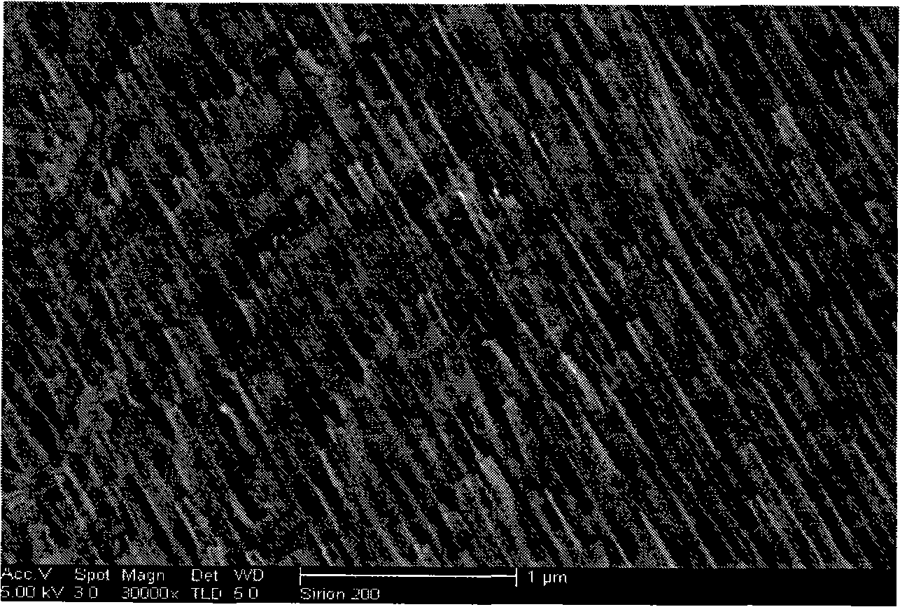
[0032] The aluminum oxide template was prepared by the secondary oxidation method, and the preparation process was as follows: after the aluminum sheet was cleaned with an organic solvent, it was annealed at 500° C. for 4 hours in nitrogen, and cooled naturally. The annealed aluminum sheet was ultrasonically cleaned with acetone, and electropolished in a polishing solution (the volume ratio of absolute ethanol to perchloric acid was 9:1). Carry out primary anodic oxidation to polished aluminum sheet, electrolytic solution is the oxalic acid solution of 0.3M, primary oxide layer is removed with the mixed acid solution of phosphoric acid (6wt%) and chromic acid (1.8wt%), then in the same condition as primary anodic oxidation Secondary anodic oxidation is carried out under certain conditions. After secondary oxidation, use saturated tin tetrachloride solution to remove the aluminum on the back, and then use phosphoric acid to expand the pores. Finally, it is washed and dried to ...

Embodiment 2

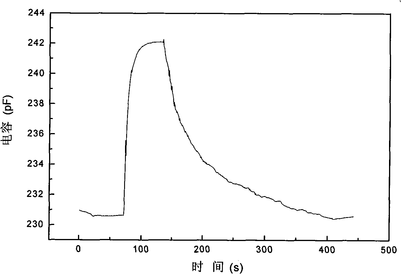
[0036] A capacitive gas sensor based on a carbon nanotube array is used to test ammonia. The capacitive gas sensor is placed in a 1-liter container, and a certain volume of ammonia gas is injected into the test box with a syringe. When the response of the capacitive gas sensor to ammonia reaches the maximum value, the gas in the test box is emptied, and then inject different volumes of ammonia gas. After repeated tests, the obtained Figure 6The capacitance change curve of the capacitive gas sensor for different test volumes of ammonia gas is shown. From Figure 6 It can be seen that the capacitive gas sensor based on carbon nanotube array has high sensitivity and still has a good response to 0.1ml of ammonia gas (about 1ppm).


PUM

PropertyMeasurementUnit
diameteraaaaaaaaaa
diameteraaaaaaaaaa

Abstract

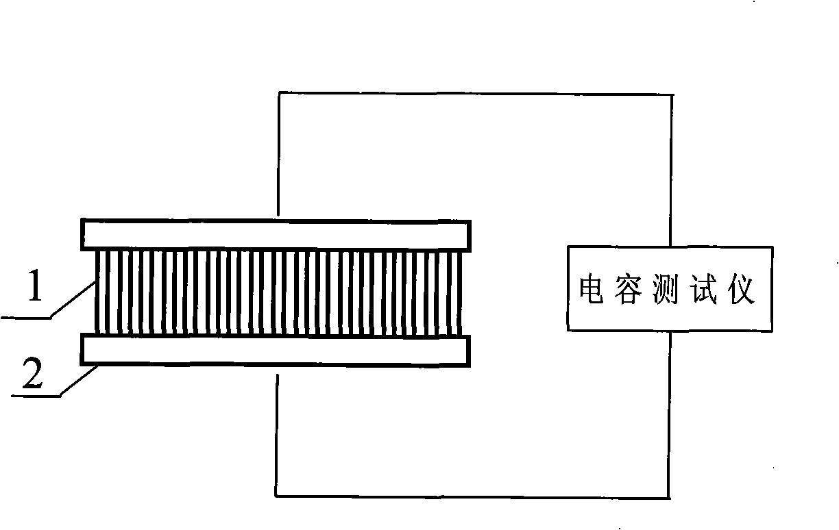
The invention discloses a capacitive gas sensor based on a carbon nanotube array and the preparation method thereof. Wherein, a capacitive gas sensor structure is composed of two flat electrodes which are respectively arranged at the upper and the lower ends of the carbon nanotube array, the carbon nanotube array, which is produced in an anodic alumina template with the method of chemical vapor deposition, is served as a support structure, which causes the space between two flat electrodes is micron-sized; the variation of the gas dielectric constant, which is flown between the two electrodes of the capacitive sensor, is represented by the variation of the capacity of the capacitive sensor, thereby the type of the tested gas can be decided. The invention avoids the deficiency in the available gas sensors, effectively shortens the space between the two electrodes of the capacitive sensor, and improves the detection sensitivity of the sensors for gas.

Description

[0001] Field [0002] The invention relates to the fields of gas detection and nanometer sensors, in particular to a capacitive gas sensor based on a carbon nanotube array and a preparation method thereof. Background technique [0003] There are many types of gas sensors, such as oxide semiconductor gas sensors, solid electrolyte gas sensors, electrochemical gas sensors, metal gate MOS gas sensors, surface acoustic wave gas sensors, infrared gas sensors, etc., among which there are many capacitive gas sensors. Literature reports. [0004] Capacitive sensors are widely used as displacement sensors, and there are many national patent technologies, such as the US patent US6946851B2 announced by the US Patent Office on September 20, 2005. There are relatively few studies on the use of capacitive sensors for gas sensors. The Chinese patent CN1234007C announced by the Chinese Patent Office on December 28, 2005 introduced a capacitive gas sensor modified by nano-molecular sieves. Th...

Claims


Application Information

Patent Timeline
Patent Type & Authority Applications(China)
IPC IPC(8): G01N27/22
Inventor 孟凡利刘锦淮李民强陈燕贾勇罗涛
Owner HEFEI INSTITUTES OF PHYSICAL SCIENCE - CHINESE ACAD OF SCI
Learn More