
Control method of electronic expansion valve

A technology of electronic expansion valve and control method, which is applied in the direction of non-electric variable control, control/regulation system, and simultaneous control of multiple variables, etc., which can solve the problem that the reliability and safety of the system cannot be guaranteed, the efficiency of the compressor is reduced, and the system operation Instability and other problems, to achieve the effect of protecting reliable and safe operation, reducing lag time, and shortening adjustment time

Active Publication Date: 2008-10-01
GREE ELECTRIC APPLIANCES INC
View PDF0 Cites 68 Cited by
  • Summary
  • Abstract
  • Description
  • Claims
  • Application Information

AI Technical Summary

Problems solved by technology

However, the capillary refrigerant flow rate and throttling degree cannot be automatically regulated, and often can only meet the requirements of certain working conditions. If the exhaust temperature and / or pressure of the system are too high, the reliability and safety of the system cannot be guaranteed, and the service life of the system is greatly reduced.
[0004] Since the effective subcooling of the refrigerant cannot be guaranteed, let alone the uniform distribution of the refrigerant, the temperature at the inlet of the compressor is too high, and the capacity of the compressor cannot be fully utilized, resulting in a decrease in the efficiency of the compressor, unstable operation of the system, and increased Problems of power consumption and waste of energy
At the same time, since the thermal expansion valve is automatically adjusted according to the superheat degree of the suction end of the system, although it has improved compared with the capillary tube, the adjustment process is obviously lagging behind, and it cannot effectively ensure that the system operates in the most suitable state, especially the heat pump water heater. When changing in real time, the lag of the adjustment process often leads to a decrease in system performance, and cannot quickly adapt to changes in various working conditions
[0005] Similarly, the refrigerant flow rate and throttling degree of the existing air-conditioning system are also difficult to automatically adjust to adapt to various working conditions, and cannot effectively ensure that the system operates in the most suitable state

Method used


Image

  • Control method of electronic expansion valve
  • Control method of electronic expansion valve
  • Control method of electronic expansion valve

Examples


Embodiment Construction

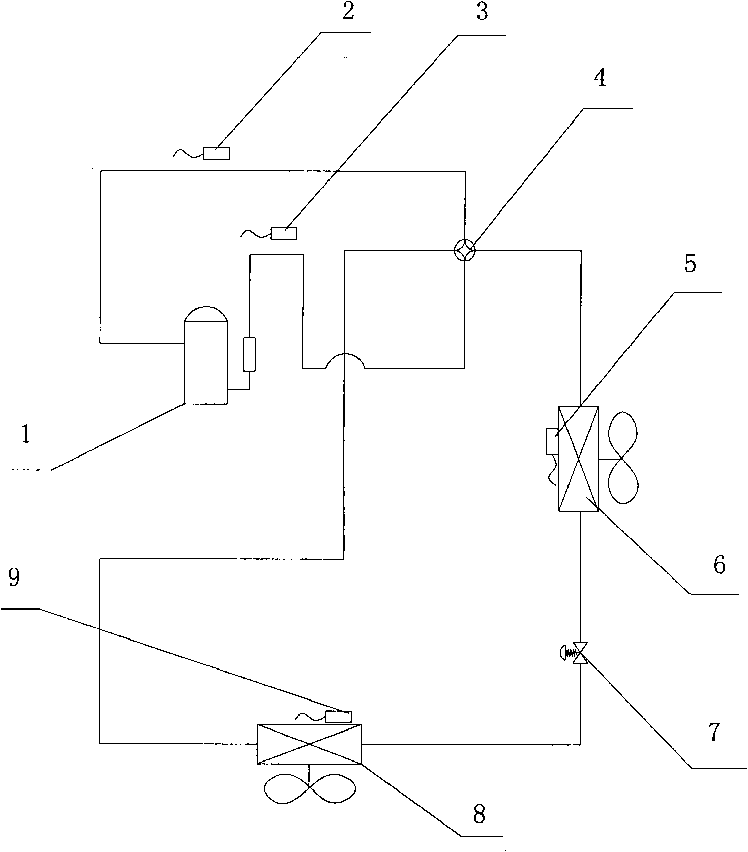
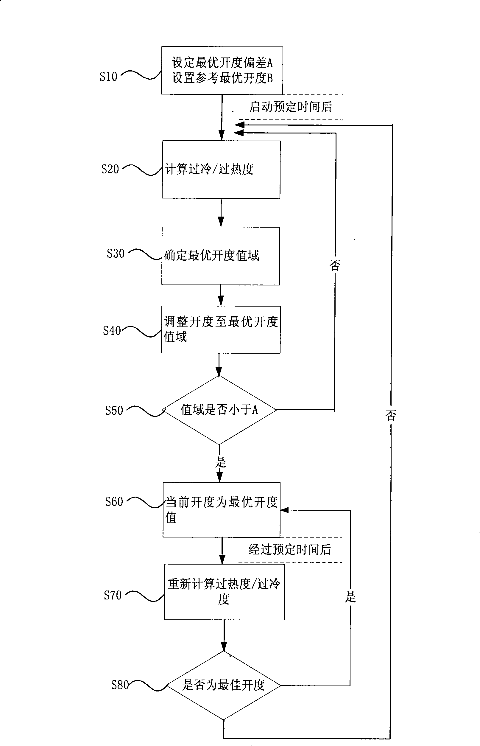
[0026] In order to facilitate understanding of the present invention, reference is made to the attached figure 1 , 2 , 3, illustrate the embodiment of the present invention, but the scope of protection of the present invention is not limited to this embodiment.

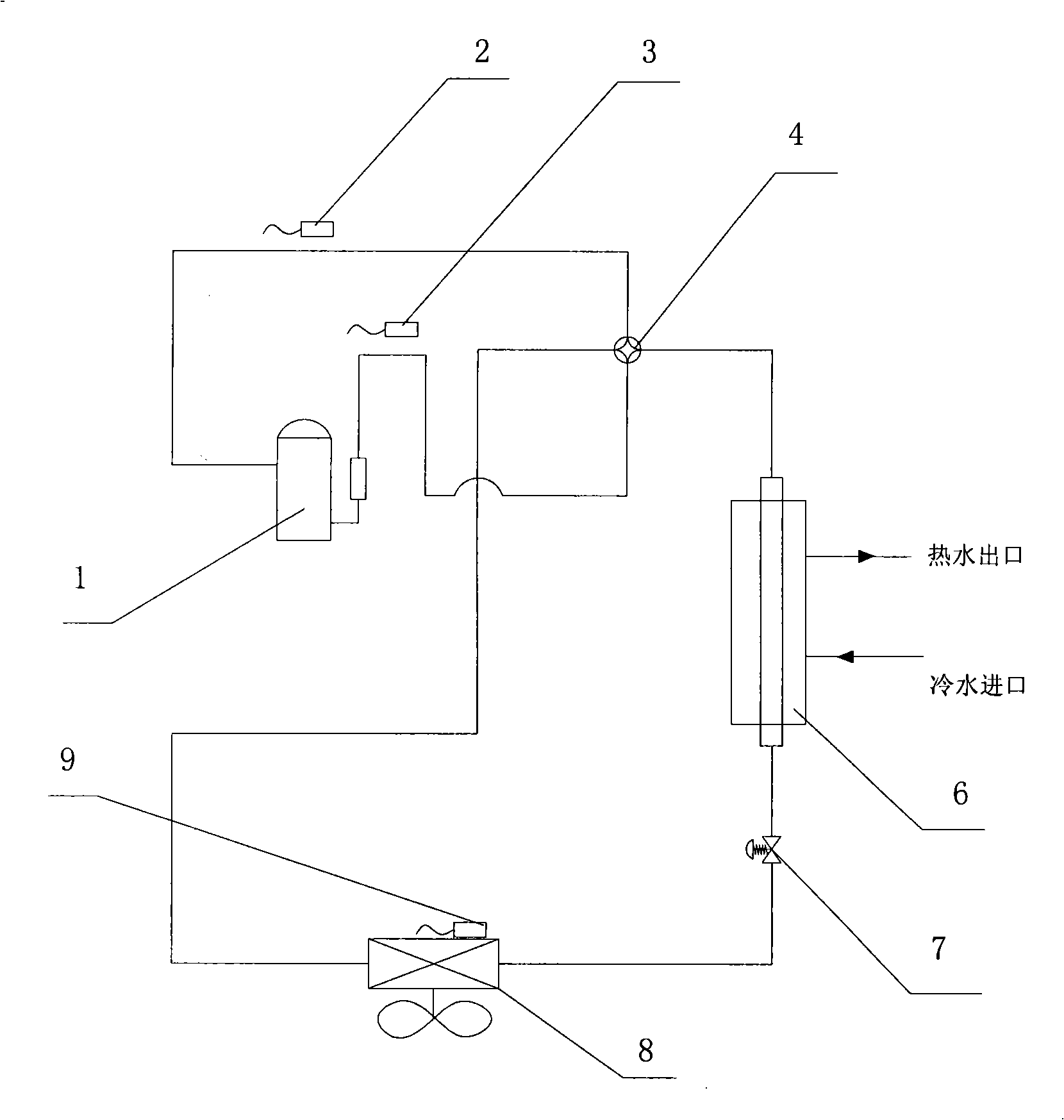
[0027] attached figure 1 The middle is the heat pump water heater system diagram. According to the operating principle of the system, as the water temperature continues to rise, the system exhaust temperature, pressure and refrigerant flow rate are constantly changing. Due to this dynamic change, the system has to perform real-time monitoring. Adaptive operation control, in which the electronic expansion valve control plays a key role, and the relevant temperature sensors include: exhaust, suction, and evaporator tube temperature sensor temperature bulbs, corresponding to labels 2, 3, and 9 respectively. The electronic expansion valve 7 presses the control flow according to each input parameter (such as image 3 sh...


PUM


Abstract

The present invention provides a control method of an electronic expansion valve, the electronic expansion valve is provided in a refrigerant circulation loop of equipment, the circulation loop is also provided with an evaporator, characterized in that the control method includes following steps: S10: starting the electronic expansion valve to process initialization, setting the opening of the electronic expansion valve in a predetermined initial value; S20: after starting the predetermined time, determining the real superheat / subcooling of the electronic expansion valve according to the difference between the outlet temperature and the inlet temperature of the evaporator; S30: comparing the object superheat / subcooling with the real superheat / subcooling, determining the optimal opening range of the electronic expansion valve; S40: adjusting the opening of the electronic expansion valve to the optimal opening range. The invention realizes the automatic control of refrigerant volume and throttle degree of equipment, and capable of adapting the working condition to control automatically, so as to protect the optimal state in the system operation ,ensuring credibility and safety operation.

Description

technical field [0001] The present invention relates to a control method for electronic expansion valves such as those used in air conditioners and heat pump water heaters. Background technique [0002] At present, in order to improve energy utilization efficiency, more and more attention has been paid to the provision of domestic hot water by heat pump water heaters. [0003] In the existing heat pump water heaters, capillary tubes or thermostatic expansion valves are generally used for throttling during heating operation, so as to achieve the purpose of hot water. However, the capillary refrigerant flow rate and throttling degree cannot be automatically regulated, and often can only meet the requirements of certain working conditions. Under these circumstances, the exhaust temperature and / or pressure of the system are too high, the reliability and safety of the system cannot be guaranteed, and the service life of the system is greatly reduced. [0004] Since the effectiv...

Claims


Application Information

Patent Timeline
IPC IPC(8): G05D27/00F25B41/06
CPCY02B30/72Y02B30/70
Inventor 张桃庄嵘柳飞陈波肖洪海
Owner GREE ELECTRIC APPLIANCES INC
Learn More