
Color wheel component

A color wheel and component technology, used in optical components, optics, instruments, etc., can solve the problems of dissipation, small heat dissipation holes, and difficult temperature reduction.

Inactive Publication Date: 2008-10-01
PRODISC TECH INC
View PDF0 Cites 4 Cited by
  • Summary
  • Abstract
  • Description
  • Claims
  • Application Information

AI Technical Summary

Problems solved by technology

[0006] Based on the above, when the color wheel assembly manufactured by the above method is installed in the projection system, it is easy to generate high temperature due to the high-speed rotation of the color wheel assembly during use. In addition, the projection system has a housing, and its The heat dissipation hole is small, and without the help of external force, the heat energy is not easy to dissipate through the heat dissipation hole, so the temperature of the color wheel assembly or other electronic components in the projection system is not easy to drop, which in turn causes the color wheel assembly or other electronic components to be easily damaged. Destruction and increased material costs
[0007] It can be seen that the above-mentioned existing color wheel assembly obviously still has inconvenience and defects in structure and use, and needs to be further improved urgently.
In order to solve the above-mentioned problems, the relevant manufacturers have tried their best to find a solution, but for a long time no suitable design has been developed, and the general products do not have a suitable structure to solve the above-mentioned problems. Urgent problem

Method used


Image

  • Color wheel component
  • Color wheel component
  • Color wheel component

Examples


Embodiment Construction

[0067] In order to further explain the technical means and effects of the present invention to achieve the intended purpose of the invention, the specific implementation, structure, characteristics and effects of the color wheel assembly proposed according to the present invention will be described below in conjunction with the accompanying drawings and preferred embodiments. Details are as follows.

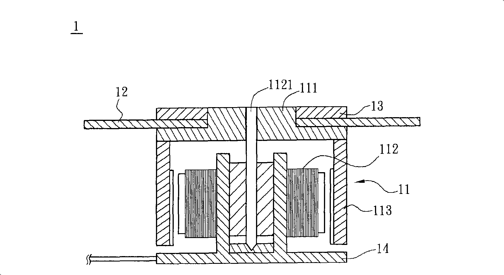
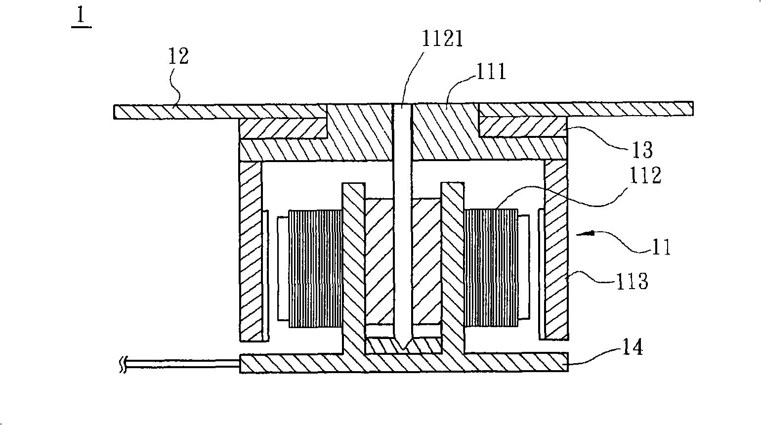
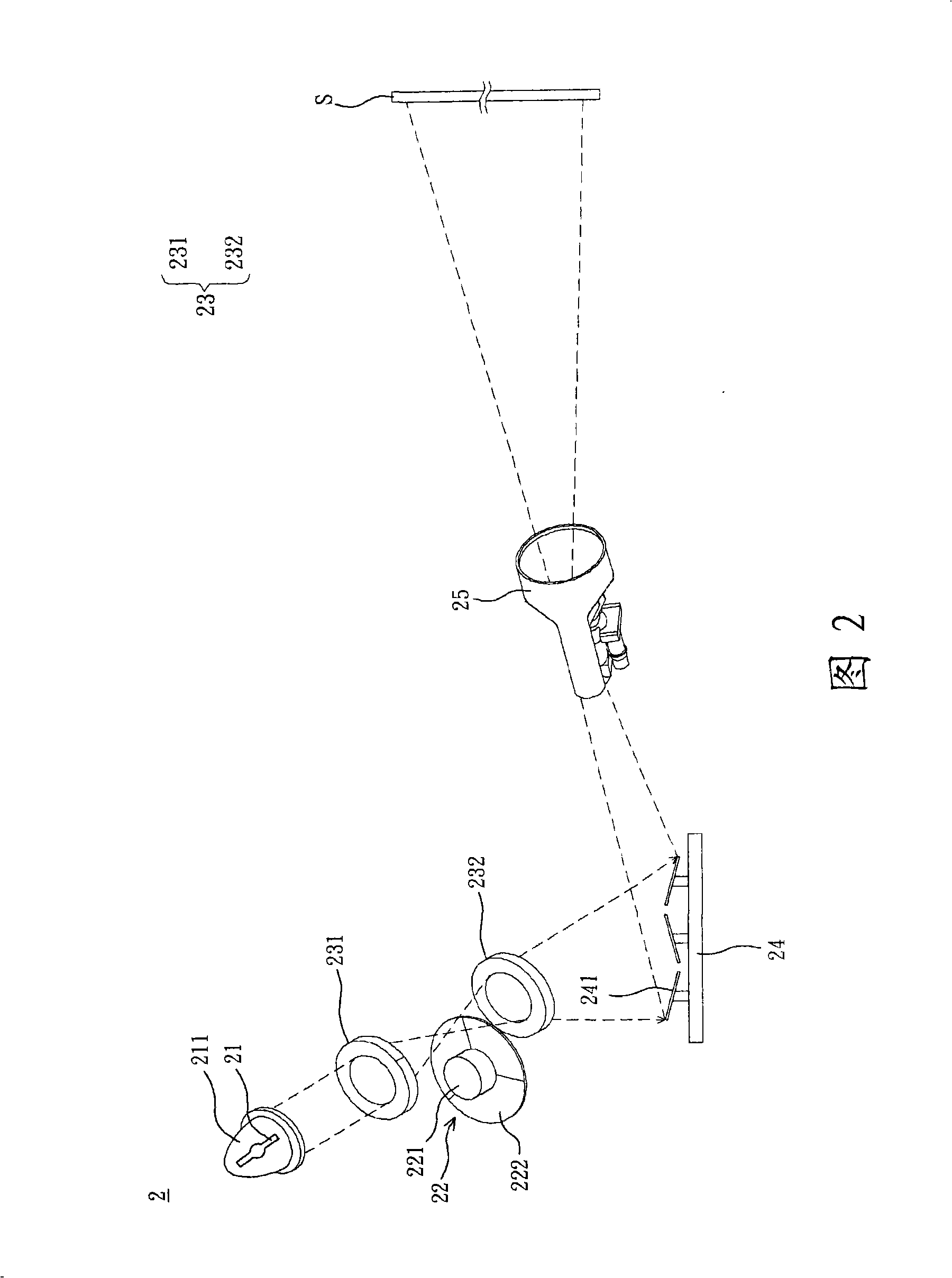
[0068] First, please refer to FIG. 2 , which is a schematic diagram of a color wheel assembly 22 of a preferred embodiment of the present invention applied to a projection system 2. In this embodiment, the projection system 2 is a digital light source processor (DLP) type projection system as an example. The projection system 2 includes a light source 21 , a color wheel assembly 22 , a projection lens 23 , a digital micromirror element 24 and a projection lens 25 .

[0069] The light source 21 is arranged in a lampshade 211, and the light source 21 emits a light. The color whee...


PUM


Abstract

The present invention provides a color wheel component, including a motor, a gasket and a color wheel. The gasket is mounted on one surface of the motor and having complex joint parts, the color wheel is mounted on the gasket and having complex filters, the filters are mounted on the joint parts respectively, and each filter has an angle with the surface of the motor. The invention makes the filter drive the surrounding air flow to form a color wheel similar to a fan by utilizing the angle formed between the filter of the motor and the surface of the motor, the heat energy is preferably dispersed by mode of air convection, and assisting air flow, capable of avoiding the damage case of the color wheel component or other electronic elements in the projection system caused by the high temperature, very pleasant to the use.

Description

technical field [0001] The invention relates to a light splitting assembly, in particular to a color wheel assembly which is not easily damaged and has a heat dissipation function. Background technique [0002] With the advancement of science and technology, the obstacles to large-scale flat panel display products have been gradually overcome, and large-size flat panel display products have gradually entered the home market. Because projection technology can provide larger and more shocking visual experience, And it is increasingly favored by users. Among the many projection devices, the Digital Light Processing (DLP) has attracted the most attention, because it has several advantages such as high brightness, short response time, no noise, light weight and short size, and has become the most popular among current projection devices. mainstream technology. [0003] The digital light source processor (DLP) type projection system adopts digital control, and utilizes the princ...

Claims


Application Information

Patent Timeline
IPC IPC(8): G03B21/14G02B5/20G02B5/23
Inventor 张光华蔡宗翰曹凯雄金克恕王志煌赖孝武虞光宇
Owner PRODISC TECH INC
Learn More