
Special micro-flow control chip and single sampling continuous separation electrophoresis method

A microfluidic chip and electrophoresis technology, applied in separation methods, filtration separation, semi-permeable membrane separation, etc., can solve problems such as buffer leakage, poor stability, and large fluctuation range of sample peak height, so as to avoid dilution and enhance repetition performance, and the effect of improving accuracy

Inactive Publication Date: 2008-10-01
DALIAN UNIV OF TECH
View PDF0 Cites 11 Cited by
  • Summary
  • Abstract
  • Description
  • Claims
  • Application Information

AI Technical Summary

Problems solved by technology

[0003] However, when the continuous electrophoresis separation experiment is carried out on the microfluidic chip with the currently commonly used entrainment sampling method, the buffer solution will leak, and the buffer solution will enter the sample solution pool through the sampling channel, resulting in the dilution of the sample solution and resulting in electrophoresis. The peak heights of multiple samples in the spectrum fluctuate widely, and the stability of multiple peak heights is very poor, which is not conducive to accurate calculation of the component content in the sample, and it is not convenient for rapid, accurate, batch and economical continuous separation and electrophoresis experiments

Method used


Image

  • Special micro-flow control chip and single sampling continuous separation electrophoresis method
  • Special micro-flow control chip and single sampling continuous separation electrophoresis method
  • Special micro-flow control chip and single sampling continuous separation electrophoresis method

Examples


Embodiment Construction

[0014] The specific implementation manners of the present invention will be described in detail below in conjunction with the technical solutions and accompanying drawings.

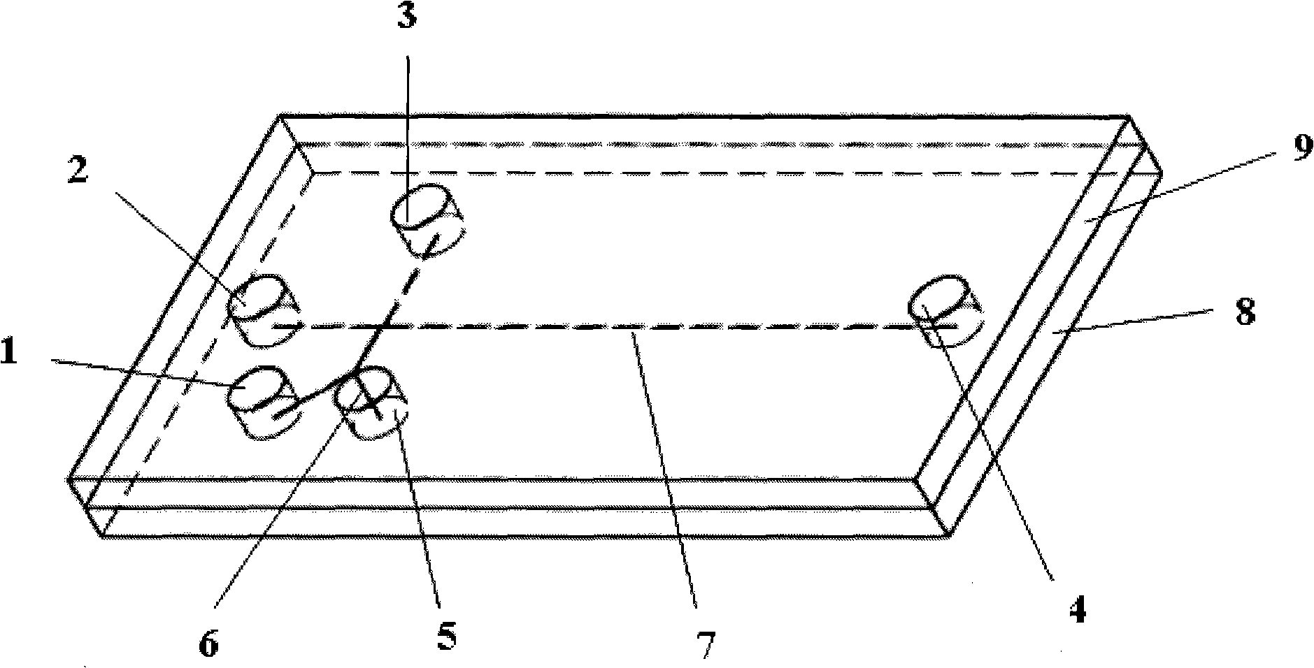
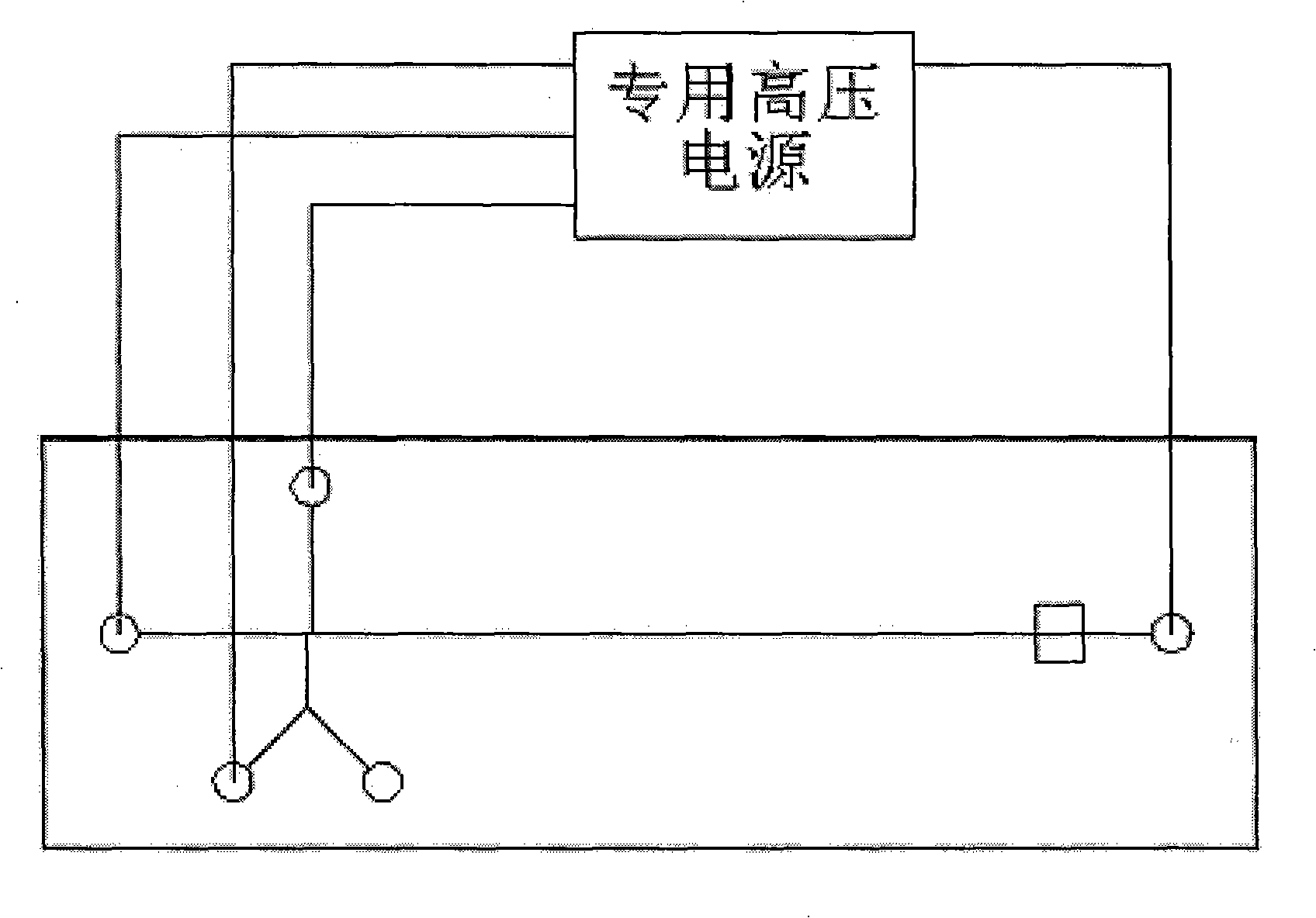
[0015] Such as figure 1 As shown, the special-purpose microfluidic chip is based on the traditional microfabrication method. The chip is composed of an upper cover 9 and a lower substrate 8. The upper cover 9 is distributed with a sample liquid pool 1 and a buffer solution with a diameter of 3 mm. Pond 2, sample waste liquid pool 3, buffer solution waste liquid pool 4, shunt liquid storage pool 5; a plurality of microchannels are distributed on the lower substrate 8, and its intersection area is double T-shaped or cross-shaped, and in the sampling groove A section of split channel 6 is added on the side wall of the channel and intersects with the original sample injection channel to form a bifurcated structure. This bifurcated structure can make the split channel 6 and the original sample injection channe...


PUM


Abstract

The present invention discloses a special microfluidic chip and a single-sampling continuous-separating electrophoresis method. The invention is applied in the technique field of the microfluidic chip in life science, medicine and analytical chemistry. The invention is characterized in that the invention comprises a method for exerting the electrophoresis high tension electricity parameter and a microfluidic chip which is used together with the method. The shunting driving voltage which is exerted to the microfluidic chip through an electrophoresis special high voltage power source leads to that the redundant buffer solution and sample solution totally flow into the shunting solution storage tank through a shunting channel. The side wall of the sampling channel on the special microfluidicchip is added with a shunting channel which forms a crossing structure with the former sampling channel and a shunting solution storage tank communicating with the shunting channel. The beneficial effects of the invention is effective prevention to the leakage of the buffer solution, avoidance to the dilution of the sample solution, evident reinforcement to the repeatability of a plurality of peak heights of the sample in the continuous-separation electrophoresis pattern and increased accuracy of the analyzing result of the continuous-electrophoresis separation experiment.

Description

technical field [0001] The invention belongs to the technical field of microfluidic chips used in life sciences, medicine, and analytical chemistry, and relates to a dedicated microfluidic chip and a single-time sample-loading continuous separation electrophoresis method, in particular to the ability to improve continuous separation electrophoresis An electrophoresis method for peak height stability and a microfluidic chip used in conjunction with the method. Background technique [0002] Microfluidic Chip (Microfluidic Chip), also known as Micro Total Analysis System (μ-TAS), integrates the processes of sample preparation, biochemical reaction, separation and detection involved in the fields of chemistry and biology into a digital square Centimeter-sized technology on a chip. When the electrophoresis is separated, a voltage is applied to both ends of the microchannel to control the flow direction and velocity of the fluid in the microchannel under the composite action of e...

Claims


Application Information

Patent Timeline
IPC IPC(8): G01N27/453B01D57/02B01L3/00B81B1/00
Inventor 刘冲陈刚王晓东徐征杜立群刘军山刘文涛
Owner DALIAN UNIV OF TECH
Learn More