
Water-saving, energy-saving and low noise oil gas dual-purpose air blast range

A blast stove, low-noise technology, applied in the field of high-efficiency, energy-saving and low-noise blast stoves, can solve the problems of heat loss, burnout of sub-fire caps, electricity consumption, etc., to reduce heat loss, reduce heat energy absorption, and reduce heat conduction. Effect

Inactive Publication Date: 2008-10-01
高学廷
View PDF0 Cites 8 Cited by
  • Summary
  • Abstract
  • Description
  • Claims
  • Application Information

AI Technical Summary

Problems solved by technology

[0003] 1. The flanges on the top of the inner and outer fire bowls are in close contact, and the heat generated by combustion is easily transferred to the outer fire bowl through the flange of the inner fire bowl, and then transferred to the outside air through the outer fire bowl, resulting in heat loss
[0004] 2. The splitter cap is set in the center of the combustion chamber. The heat generated by the combustion can easily burn the splitter cap. The gas hole on the splitter cap is small and easily blocked by carbon deposits.
[0006] 4. The stove ring of the existing gas blast stove is a solid body, which is easy to be burned out. Since cooking is mostly used on a large fire, the firepower is as high as 50,000 calories. After the stove ring is red, its heat will be directly transferred to the stainless steel of the stove below On the surface, in order to protect the cooking surface from barbecue deformation, it is necessary to use water flushing to cool down; the water consumption is very large, 2-3 tons of clean water per hour, and the water flows directly into the sewer from the cooking surface, and the water and waste heat are all wasted
[0007] Five, the burner of existing gas blast stove has only big fire, does not have permanent flame (small fire), and ignition is very inconvenient
[0008] 6. The existing burner needs to be equipped with a medium-pressure fan, such as a 250-watt fan, which is costly, consumes electricity, and is noisy

Method used


Image

  • Water-saving, energy-saving and low noise oil gas dual-purpose air blast range
  • Water-saving, energy-saving and low noise oil gas dual-purpose air blast range
  • Water-saving, energy-saving and low noise oil gas dual-purpose air blast range

Examples


Embodiment Construction

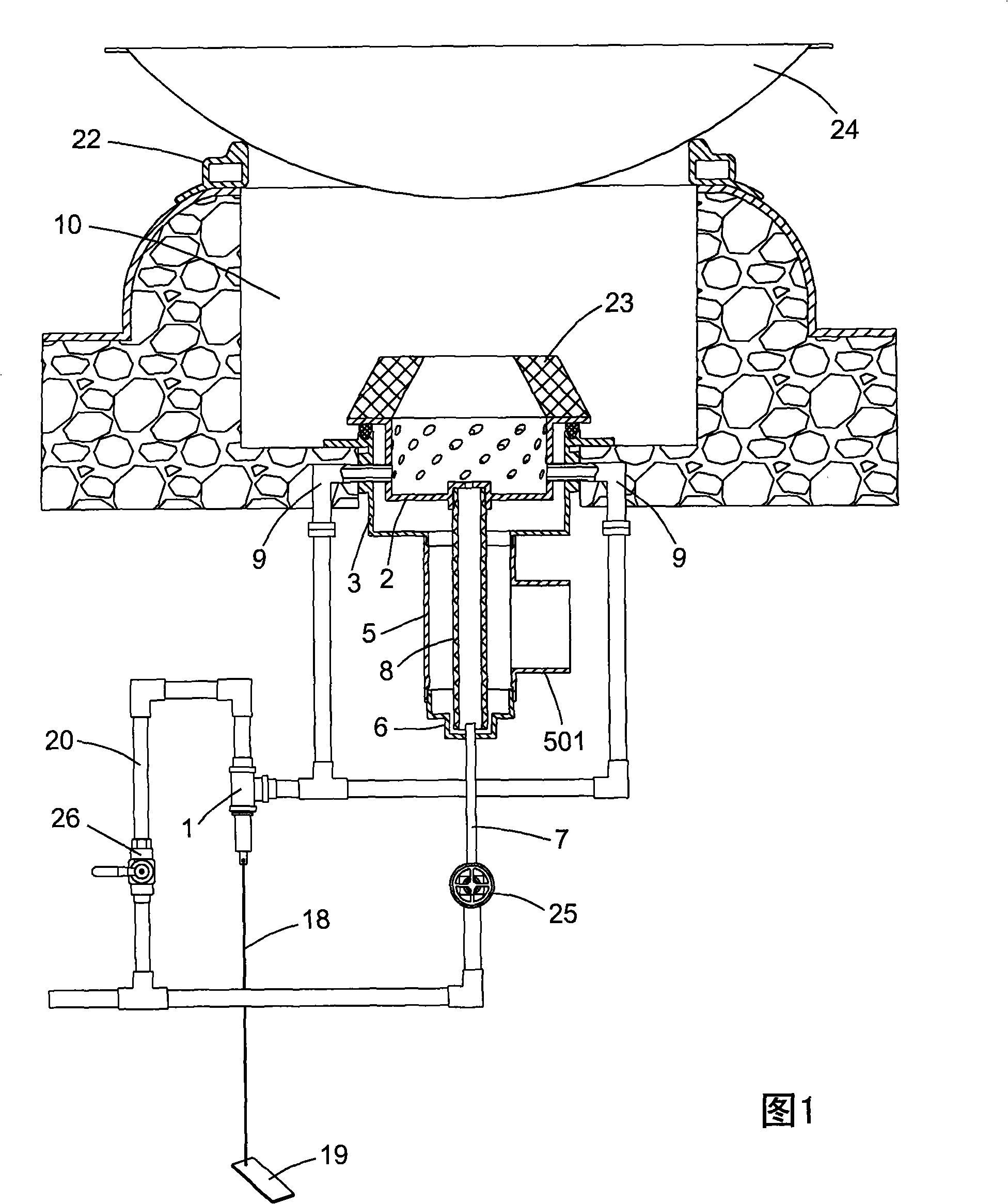
[0031] Label in the figure

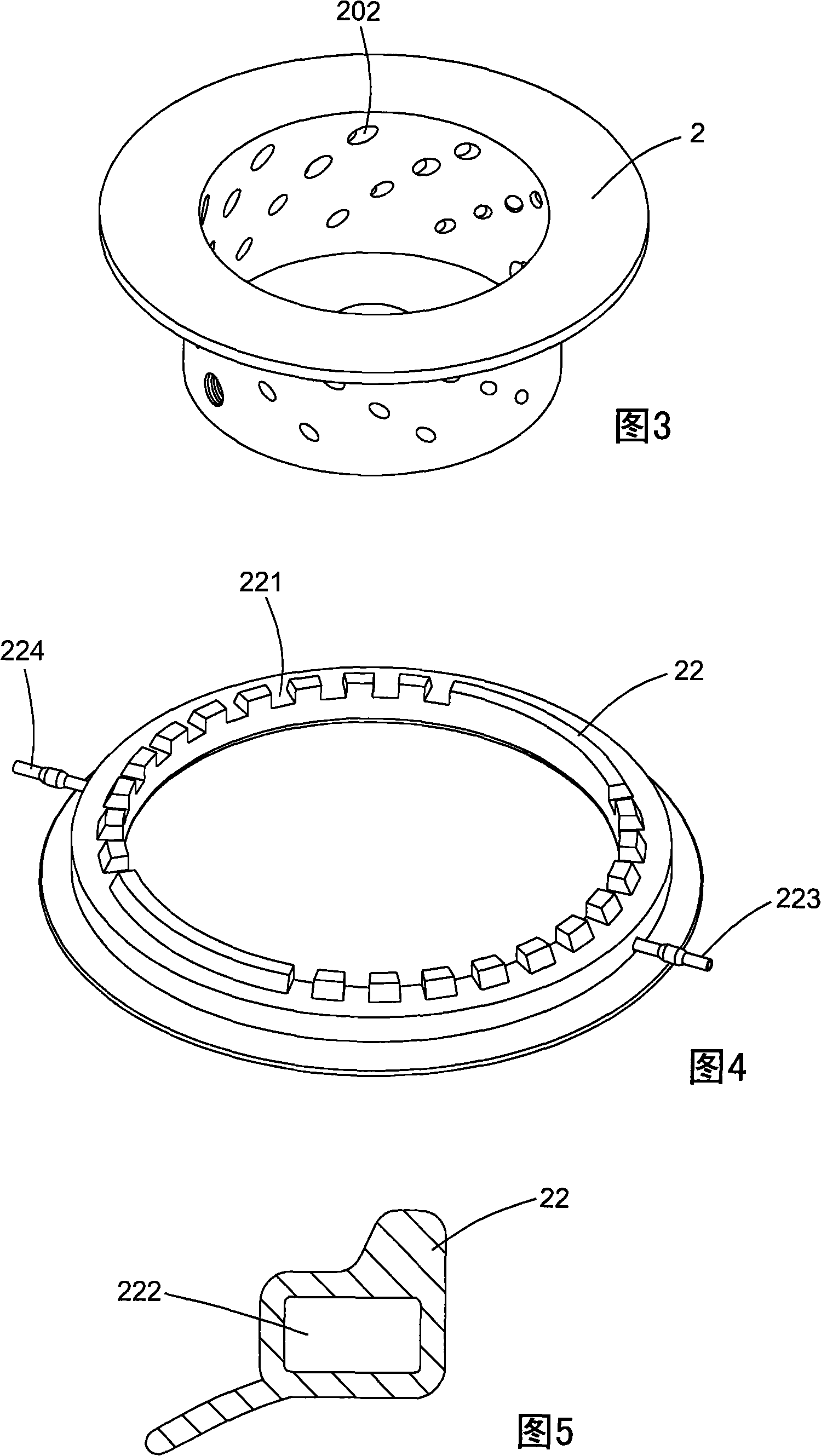
[0032] 1 foot valve 2 inner fire bowl

[0033] 201 Pipe head cap seat 202 Wind eye 203 Flange plate 204 Air outlet

[0034] 3 outer fire bowl 301 groove 303 flange

[0035] 4 air channel 5 air duct 501 nozzle

[0036] 6 plug 601 pipe head base 602 gap

[0037] 7 Auxiliary gas supply pipe 8 Casing pipe 9 Inlet pipe 10 Stove chamber

[0038] 11 valve body 111 inlet 112 outlet 113 valve port

[0039] 12 Stem 13 Disc 14 Stem Seat

[0040] 15 first spring 16 second spring 17 retaining ring 18 traction rope 19 pedal

[0041] 20 main gas supply pipe 21 insulation pad 22 stove ring 221 gap

[0042] 222 inner cavity 223 water inlet pipe 224 water outlet pipe

[0043] 23 fire ring 24 pot 25 needle valve 26 ball valve

[0044] 27 sealing ring 28 sealing ring 29 gasket

[0045] 30 nozzle 31 elbow 32 inner fire bowl 321 wind eye

[0046] 33 outer fire bowl 34 air cap 341 air eye

[0047] 35 intake pipe 36 screw 37 screw

[0048] Please refer to Fig...


PUM


Abstract

A water saving and energy saving low noise oil gas dual purpose blast hearth, wherein the burner is composed of an inner and an outer fire vessels, the top nozzle of the wind pipe is screwed on the bottom pot of the outer fire vessel, the bottom nozzle of the wind pipe is screwed with a pipe plug, the center of which is provided with a tubing head base, the central hole of the tubing head base is communicated with a fuel gas assistant burning supply pipe, the center of the inner fire vessel if provided with a tubing head cap seat, the center of which is provided with an air outlet. The center of the wind pipe is equipped with a sleeve, the upper end of which is screwed with the tubing head cap seat, while the lower end is in gap matched with the tubing head cap seat. The central nozzle of the wind pipe is connected with a fan, a heat insulating mattress is arranged between the flange on the inner fire vessel upper part and the circular flange of the outer fire vessel upper part, the side walls of the inner and the outer fire vessels are opened with screws, and the air inlet pipe traversely passes through the interlining chamber between the inner and the outer fire vessels to screw with the bolt hole. The invention is provided with conflagration and nagaaki fire, which controls the conflagration by the foot valve to save fuel gas; and provided hot water using the remaining heat, meanwhile reduces the temperature of the hearth, saves water with small fan and low noise.

Description

technical field [0001] The invention relates to fuel oil and gas stoves, in particular to a high-efficiency, energy-saving and low-noise blast stove. Background technique [0002] The burner of existing gas-fired stove is mainly made of inner and outer fire bowls, the tops of the inner and outer fire bowls have corresponding flanges, and the flanges of the inner and outer fire bowls are in close contact and fastened by screws. There is an air distribution cap in the middle of the inner fire bowl, and air holes are opened on the air distribution cap, and air holes are opened on the side wall of the inner fire bowl. The interlayer between the inner and outer fire bowls is an air chamber, which communicates with the blower. Under the action of the blower, the air in the air chamber is ejected from the air eye, mixed with the fuel ejected from the air eye, and burned in the inner cavity (combustion chamber) of the inner fire bowl. This burner mainly has the following disadvanta...

Claims


Application Information

Patent Timeline
IPC IPC(8): F24C1/02F24C13/00
Inventor 高学廷
Owner 高学廷
Learn More