Thermal optimization of a solar photovoltaic powered electrolyzer system

A technology of solar photovoltaic and electrolyzer, applied in the field of solar electrolyzer, can solve the problems of high cost and low efficiency of solar hydrogen

Inactive Publication Date: 2011-07-06
GM GLOBAL TECH OPERATIONS LLC
View PDF0 Cites 4 Cited by
  • Summary
  • Abstract
  • Description
  • Claims
  • Application Information

AI Technical Summary

Problems solved by technology

However, the development of solar hydrogen generation using photovoltaic-electrolyzer (PV-electrolyzer) systems is limited by low efficiency (2-6%) and high cost (>$11 / kg H 2 ) are delayed

Method used


Image

  • Thermal optimization of a solar photovoltaic powered electrolyzer system
  • Thermal optimization of a solar photovoltaic powered electrolyzer system
  • Thermal optimization of a solar photovoltaic powered electrolyzer system

Examples


Embodiment Construction

[0017] The following description of the embodiments is merely exemplary in nature and in no way intended to limit the invention and its application or use.

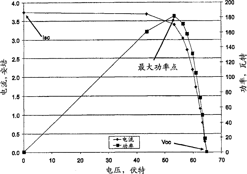
[0018] figure 1 Shown are current-voltage (I-V) curves and power-voltage curves measured for a Sanyo HIP-190BA3 module supplied by Sanyo Energy Corp. in Warren, Michigan on a sunny day. The module is pointed at the sun, using a DC load (HewlettPackard 6060A) from the open circuit voltage (V oc ) to the short-circuit current (I sc ) scan to obtain the I-V curve. Solar irradiance was measured with a United Detector Technology crystalline silicon photodiode (UDT 10 Model DP / SV) hooked up to a Fluke Model 179 multimeter that measures the mA current from the photodiode. 1000W / m 2 The UDT output current at irradiance was calibrated by the National Renewable Energy laboratory. The temperature of the module was measured by a VWR catalog number 77776-730 (Batavia, Illinois) electronic thermometer affixed to the back of the mo...


PUM


Abstract

One embodiment of the invention includes a process comprising transmitting electrical power produced by a PV array to an electrolyzer and transferring heat from the PV array to the electrolyzer. The resulting process produces renewable hydrogen from solar energy at a lower cost per kg.

Description

technical field [0001] The field to which the invention generally relates includes solar electrolyzers. Background technique [0002] Certain hydrogen generating devices use electrical energy to generate hydrogen (and oxygen) through the electrolysis of water in an electrolyzer. The resulting hydrogen is stored for use as fuel, which can be used in fuel cells, internal combustion engines, and home-based hydrogen fuel systems. Oxygen can be vented to the atmosphere. The electrolyzer can be powered by solar energy. Solar hydrogen generation using photovoltaics-electrolyzers (PV-electrolyzers) is a renewable and environmentally friendly energy source. Shifting the U.S. fuel supply to renewable energy is necessary for sustainable transportation, sustainable economic growth, reduced greenhouse gas emissions, and national energy security (by displacing polluting fossil fuel imports from unstable regions overseas) indispensable. However, the development of solar hydrogen gener...

Claims


Application Information

Patent Timeline
IPC IPC(8): H01L31/052
CPCY02B10/20Y02E70/10Y02B10/70Y02B10/10C25B15/00C25B1/04Y02E60/366Y02E60/36Y02P20/133Y02T10/7072C25B1/55C25B15/021
Inventor N·A·凯利T·L·吉布森
Owner GM GLOBAL TECH OPERATIONS LLC
Why Eureka
Try Eureka