
Laser holograph mould pressing device

A laser holographic and graphic technology, applied in printing, rotary printing machines, printing machines, etc., can solve the problems of difficult processing of cam 07, indentation of molded material 08, deformation of cam 07 contour, etc., and achieve good product quality and operation Stable, non-abrasive effect

Active Publication Date: 2011-04-20
广东东峰新材料集团股份有限公司
View PDF0 Cites 0 Cited by
  • Summary
  • Abstract
  • Description
  • Claims
  • Application Information

AI Technical Summary

Problems solved by technology

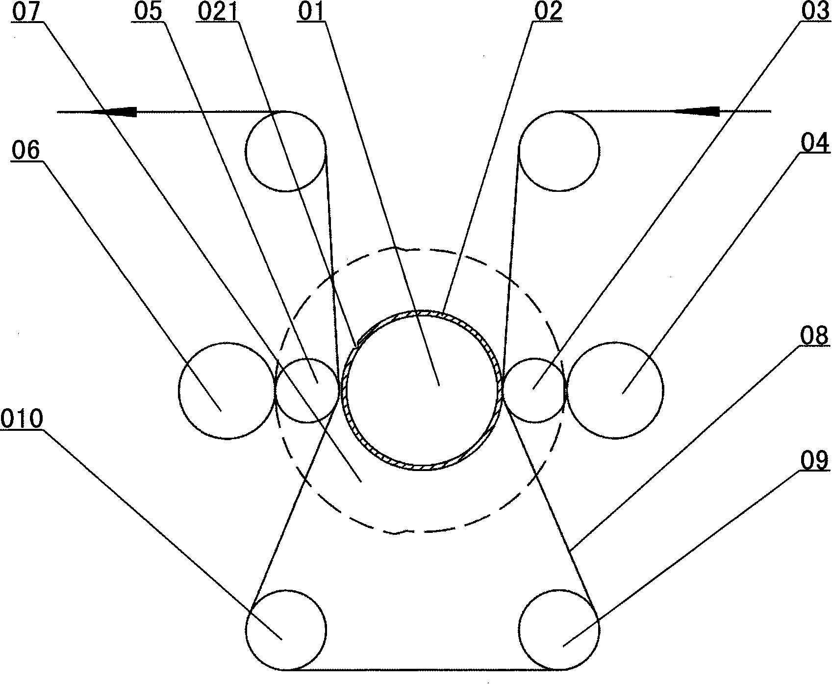
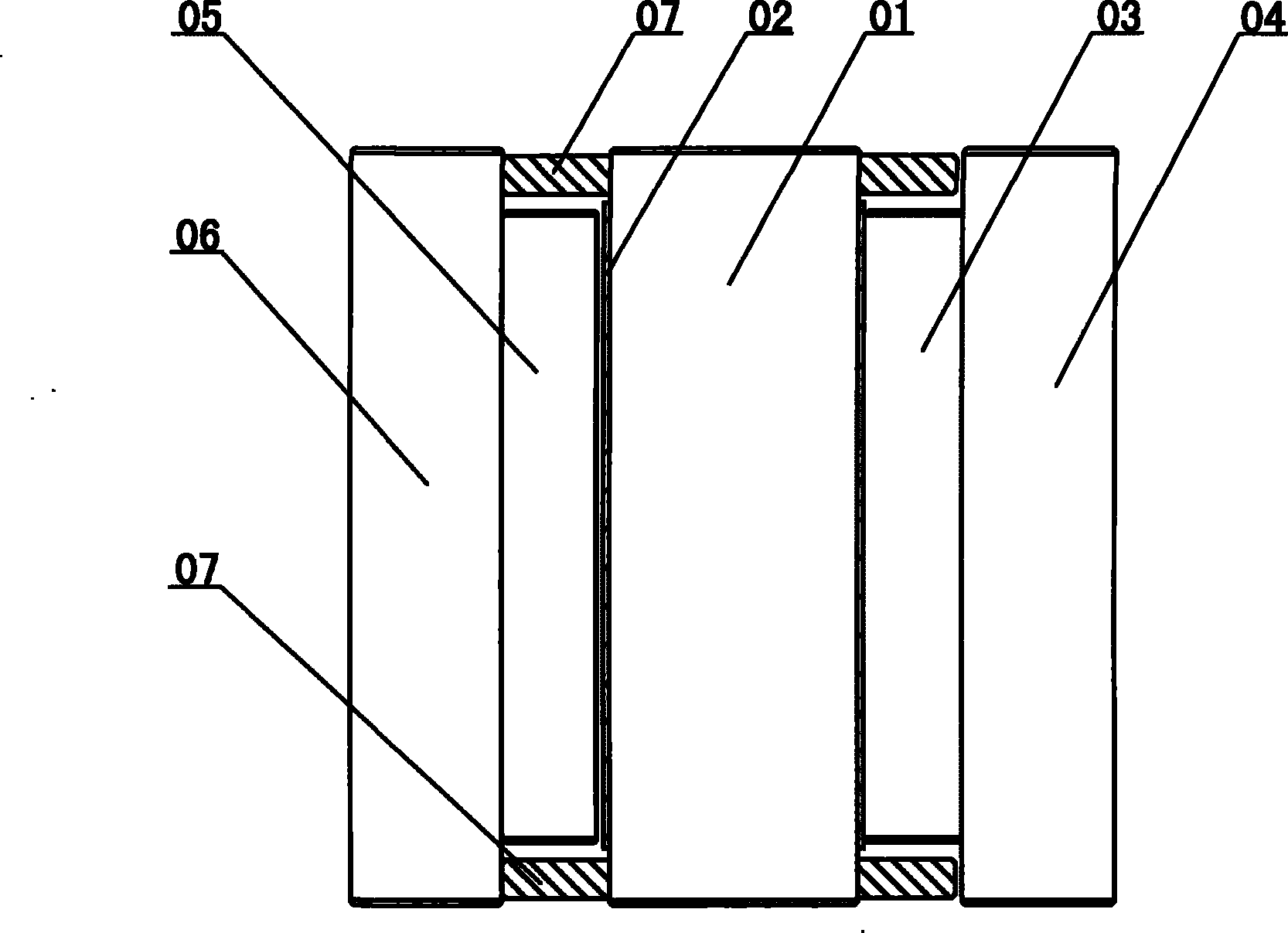
However, in the production process of this laser holographic image and text molding device, the pressure between the first pressing roller 03, the second pressing roller 05 and the version roller 01 is changed by the cam 07, and the pressure between the first molding station and the second molding station is changed. To achieve intermittent embossed laser holograms, due to the need to produce periodically changing pressure, when the first pressure roller 03 or the second pressure roller 05 presses against the plate roll 01 and leaves the plate roll 01, a huge impact force is generated, which is easy to cause Indentation occurs on the molding material 08, which affects product quality; in addition, the processing of the cam 07 is difficult, and repeated adjustments are required during installation to keep the laser hologram molding device in good condition. Moreover, the cam 07 is easy to wear during the production process, resulting in The profile of the cam 07 is deformed, resulting in inaccurate pressure changes between the first press roller 03 and the second press roller 05 and the plate roller 01, which adversely affects product quality

Method used


Image

  • Laser holograph mould pressing device
  • Laser holograph mould pressing device
  • Laser holograph mould pressing device

Examples


Embodiment Construction

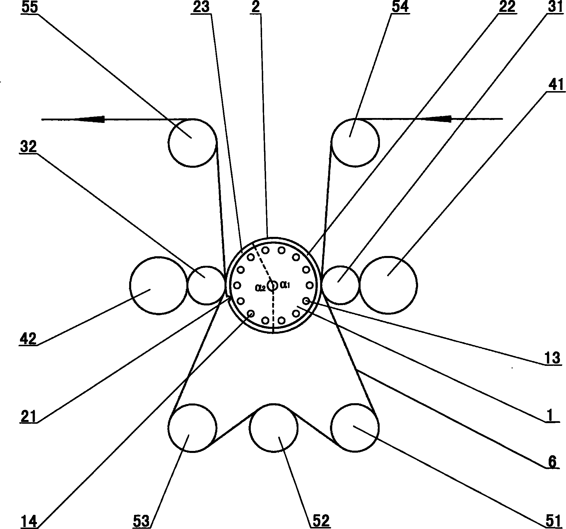
[0027] Such as image 3 As shown, the laser holographic image-text embossing device comprises a plate roll 1, a molded working plate 2, two pressure rolls (ie, pressure roll 31 and pressure roll 32) and two back pressure rolls (ie, back pressure roll 41 and back pressure roll 42).

[0028] refer to Figure 4 , the surface of the version roller 1 is divided into a high temperature zone 11 whose temperature reaches the molding working temperature and a low temperature zone 12 whose temperature is lower than the molding working temperature. Parallel straight lines 15 and 16; where the high temperature region 11 occupies four sevenths of the surface of the plate roller 1, and the low temperature region 12 accounts for three sevenths of the surface of the plate roller 1, that is, the central angle α1 corresponding to the high temperature region 11 is about 205.7° , the central angle α2 corresponding to the low temperature region 12 is about 154.3°. The temperature range of the h...


PUM


Abstract

The invention relates to a laser holography graph-text stamping device. The device comprises a cylinder and a stamping working plate, and the stamping working plate is installed on the cylinder. The device is characterized in that: the surface of the cylinder is divided into a high temperature area the temperature of which reaches the stamping working temperature and a low temperature area the temperature of which is lower than the stamping working temperature; the positions of the joints of the two ends of the stamping working plate correspond to the low temperature area on the surface of the cylinder; the device also comprises at least two compression rollers, and the compression rollers are arranged along the circumferential direction of the cylinder and respectively pressed with the cylinder. At least two stamping working positions are formed by the device of the invention, the laser holography graph-text stamped by each stamping working position is subsequently connected, the positions of the joints of the two ends of the stamping working plate correspond to the low temperature area temperature of which is lower than the stamping working temperature on the surface of the cylinder and no plate joints corresponding to the joints are generated at the stamping materials; the device of the invention has easy and fast installation and testing processes, stable operation, good product quality, wear resistance and long service life, and the product quality can be long-term maintained.

Description

technical field [0001] The invention relates to a laser hologram text molding device capable of pressing out laser hologram text on a molding material. Background technique [0002] The laser hologram embossing method includes the following steps: first obtain the laser hologram through holography or computer laser holographic simulation design; then reproduce the laser hologram on the master plate through a laser engraving machine; the master plate is copied into Nickel version (i.e. molded working version); the nickel version is installed on the molding machine, and the nickel version is heated and pressed on the molding surface of the molding material (the molding material is usually a film, such as OPP film (oriented polypropylene film), PET film ( polyester film), laser holograms can be pressed on the molding surface of the molded material, and the molded material with laser holograms is commonly called laser film. The laser film can be aluminized, compounded, and peele...

Claims


Application Information

Patent Timeline
Patent Type & Authority Patents(China)
IPC IPC(8): B41F19/02B41F13/10
Inventor 黄炳文黄佳儿陆维强谢名优何兴万张俊健
Owner 广东东峰新材料集团股份有限公司
Learn More