Pump

A fluid and vibrating plate technology, used in pumps, piston pumps, pumps with flexible working elements, etc., can solve the problems of reducing fluid discharge, diaphragm damage, inability to exert performance, etc., to achieve large discharge and restrain expansion and deformation. , the effect of increasing the amount of movement

Inactive Publication Date: 2008-09-24
MINORU IND
View PDF2 Cites 10 Cited by
  • Summary
  • Abstract
  • Description
  • Claims
  • Application Information

AI Technical Summary

Problems solved by technology

[0011] When this deformation in the opposite direction occurs on the diaphragm, the discharge volume of the fluid will be reduced, not only the original performance cannot be exerted, but also the diaphragm is likely to be damaged. Therefore, it is necessary to prevent the diaphragm from being deformed in the opposite direction to the driving direction. With a diaphragm pump, there is a problem that it is difficult to obtain a high discharge pressure

Method used


Image

  • Pump
  • Pump
  • Pump

Examples


Embodiment Construction

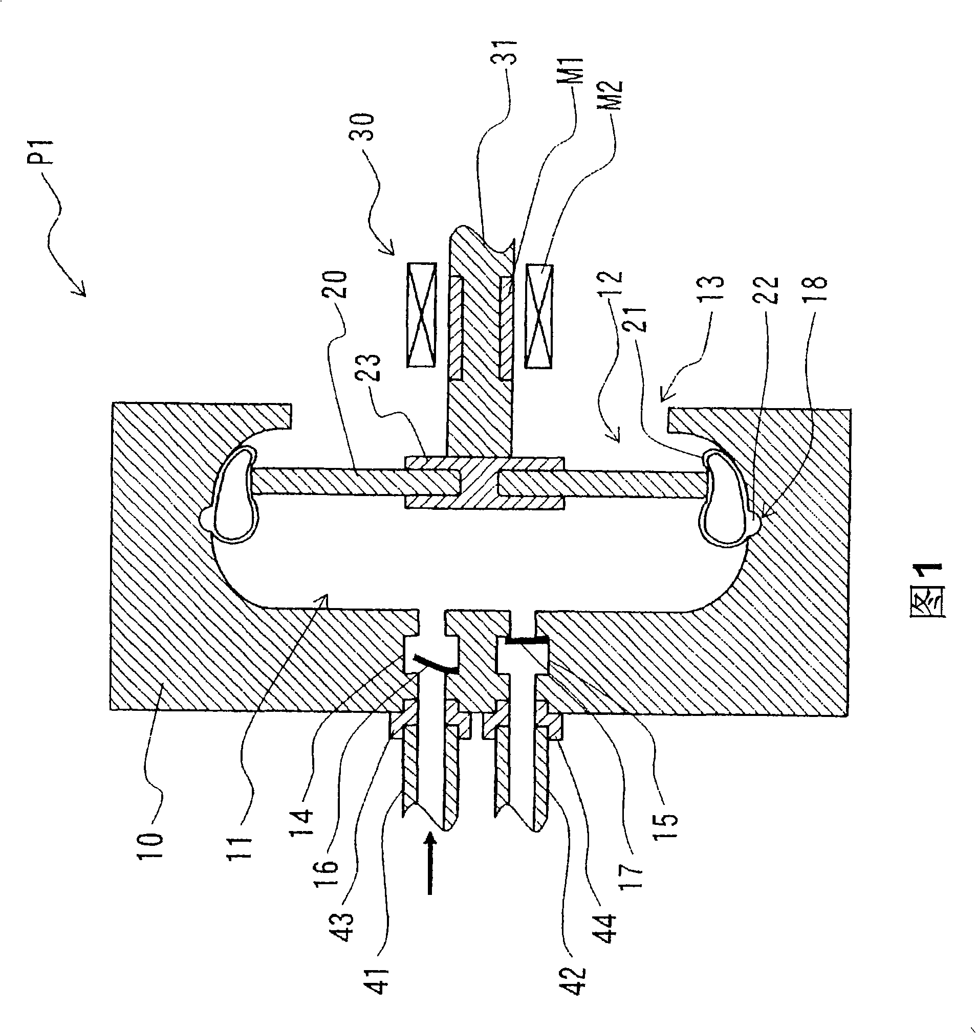
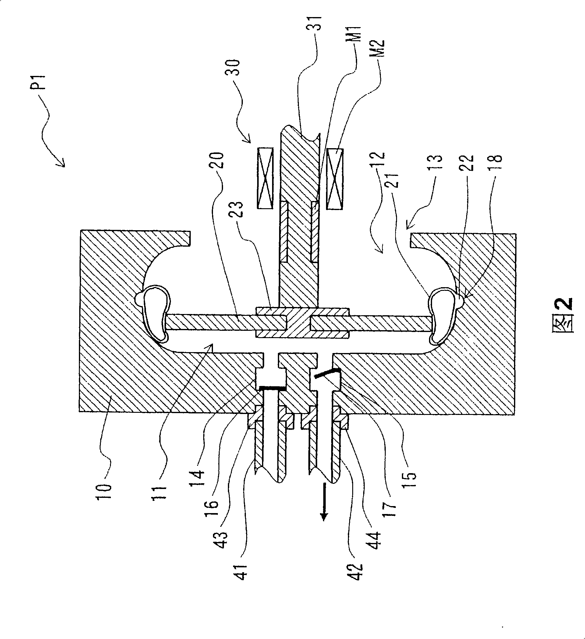
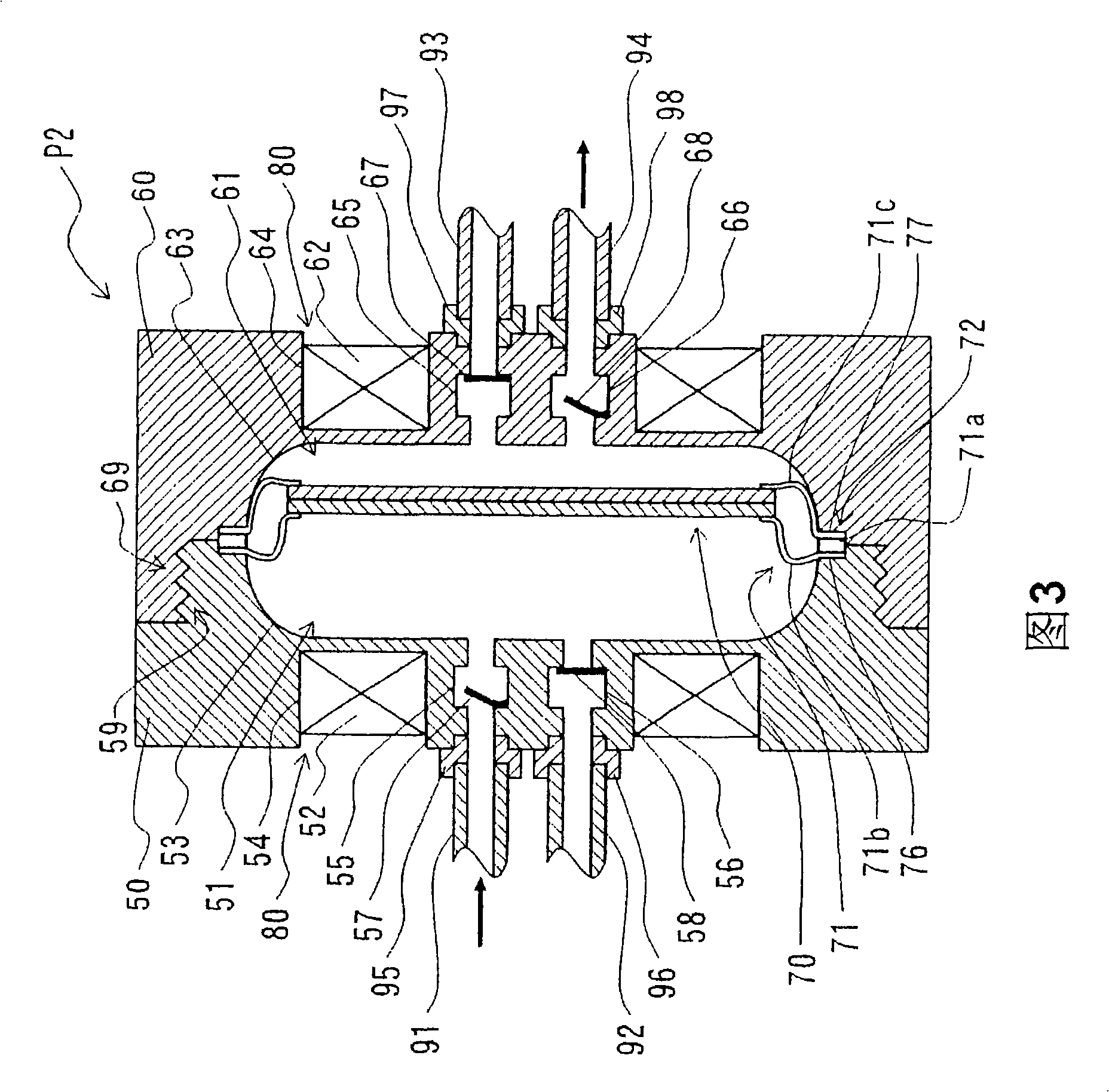
[0057] The pump of the present invention applies a predetermined pressure to feed a low-viscosity fluid such as air, and realizes a high discharge pressure of a so-called diaphragm pump.

[0058] That is to say, the pump of the present invention is the same as a common diaphragm pump, comprising: a housing with a storage chamber that connects the feed pipe and the delivery pipe respectively through the one-way valve and temporarily stores the fluid; Driving the vibrating body that sucks the fluid from the feed pipe to the storage chamber and then extruding it to the delivery pipe; and the driving part that drives the vibrating body forward and backward.

[0059] A common diaphragm pump uses a film-like diaphragm to form a vibrating body, but the present invention uses a plate with higher rigidity to form a vibrating plate.

[0060] Further, the vibrating plate is provided with an annular pipe along the outer periphery, the vibrating plate is attached to the case through the pi...


PUM


Abstract

A diaphragm type pump for feeding a low viscosity fluid such as air under high pressure while minimizing the size of a feeding means. The pump connected with a feeding pipe and a delivery pipe and delivering fluid fed from the feeding pipe from the delivery pipe, comprises a housing provided with a storage chamber communicating with the feeding pipe and the delivery pipe through a one-way valve, respectively, and storing the fluid temporarily, a diaphragm arranged oppositely to the storage chamber and driven to advance or retract thus sucking the fluid from the feeding pipe into the storage chamber and then pushing out the fluid to the delivery pipe, and a section for driving the diaphragm to advance or retract. The diaphragm is provided with a ring-like tube along the outer circumferential edge thereof, and the diaphragm is fixed to the housing through the tube thus advancing or retracting the diaphragm while deforming the tube elastically.

Description

technical field [0001] The present invention relates to a diaphragm type pump that feeds a fluid by driving a plate-shaped vibrating plate forward and backward instead of a diaphragm of a diaphragm pump. Background technique [0002] Conventionally, a diaphragm pump is generally used as a driving source for fluid feeding. This type of diaphragm pump is provided with a storage chamber for temporarily storing a fluid in a casing constituting the outer frame of the diaphragm pump, and a diaphragm is arranged facing the storage chamber. At the same time, the storage chamber is connected with the feeding pipe and the sending pipe respectively through the one-way valve. [0003] Through the elastic deformation of the diaphragm and the backward state relative to the storage chamber, the pressure in the storage chamber can be reduced, thereby attracting the fluid from the feed pipe into the storage chamber; through the elastic deformation of the diaphragm relative to the storage ch...

Claims


Application Information

Patent Timeline
Patent Type & Authority Applications(China)
IPC IPC(8): F04B43/04F04B9/08F04B19/22F04B35/00
CPCF04B43/0036F04B43/0054F04B43/04
Inventor 则次俊郎高野和洁
Owner MINORU IND
Why Eureka
Try Eureka