
Experimental device for concrete multifactor permanent stability under co-action of pulling stress and surroundings

A technology that works together and is an experimental device. It is used in measuring devices, strength characteristics, material inspection products, etc. It can solve problems such as difficult coincidence, damage at clamping, and easy eccentricity. Accurate geometry, small footprint, No stress relaxation effect

Inactive Publication Date: 2008-09-24
SOUTHEAST UNIV
View PDF0 Cites 41 Cited by
  • Summary
  • Abstract
  • Description
  • Claims
  • Application Information

AI Technical Summary

Problems solved by technology

There are two main reasons for this: ①The design and processing of the test device for applying tensile stress is very difficult, and it is difficult to ensure that the axis of the tensile sample coincides with the line of action of the tensile load during the test. Great discreteness; ②The tensile sample and the tensile chuck are prone to stress concentration at the clamping point, causing the sample to fail at the clamping point instead of breaking in the middle
[0005] The above shortcomings severely limit the wide application of direct tensile stress loading devices in concrete multi-factor durability experiments.

Method used


Image

  • Experimental device for concrete multifactor permanent stability under co-action of pulling stress and surroundings
  • Experimental device for concrete multifactor permanent stability under co-action of pulling stress and surroundings
  • Experimental device for concrete multifactor permanent stability under co-action of pulling stress and surroundings

Examples


Embodiment Construction

[0034] The present invention will be further described below in conjunction with accompanying drawing:

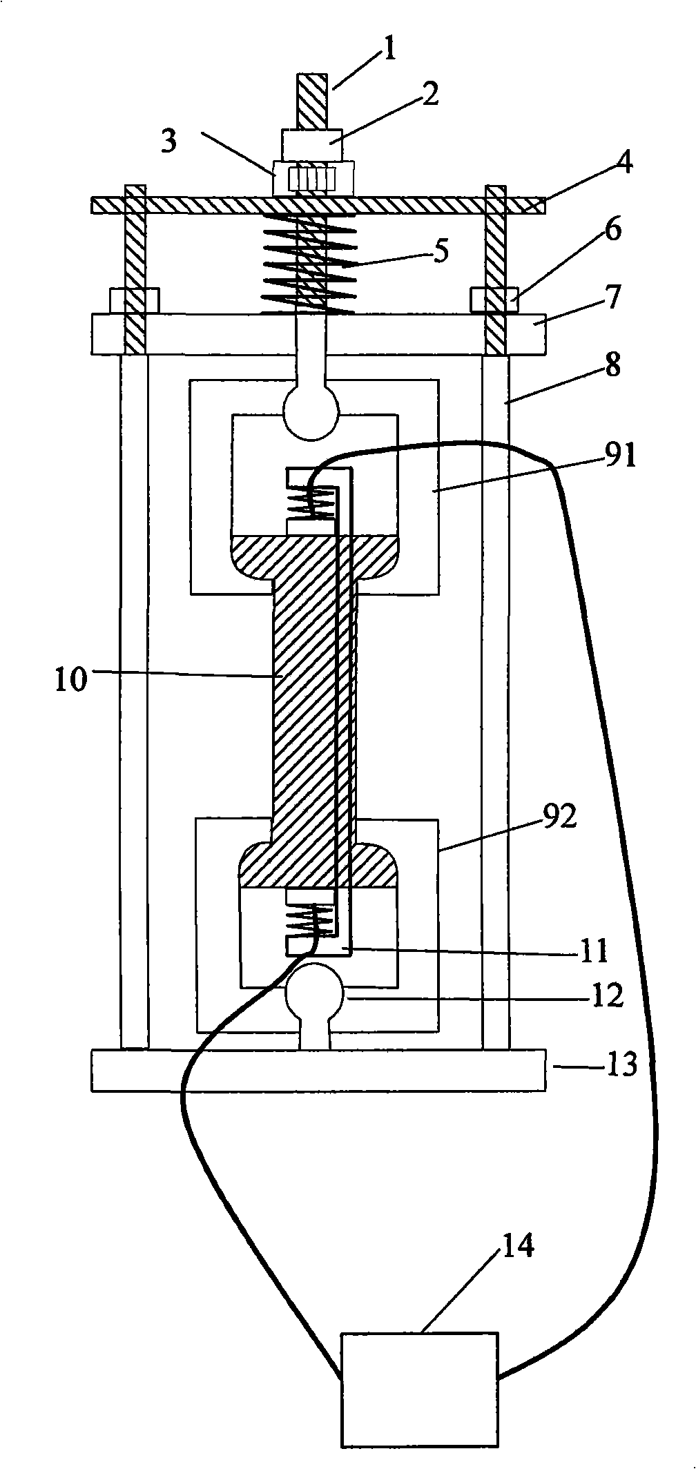
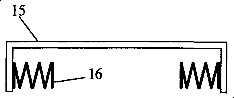
[0035]The device includes: spherical screw 1, nut 2, stress sensor 3, limit plate 4, spring 5, lock nut 6, upper pull plate 7, pull rod 8, tensile chuck, dumbbell-shaped concrete specimen 10, constant Force clamping instrument 11, spherical pull rod 12, pull-down plate 13, non-metallic ultrasonic tester 14; in this device, the lower part of pull rod 8 is connected with pull-down plate 13, and the upper part of pull rod 8 passes through upper pull plate 7 and limit plate 4 , the upper pull plate 7 is worn on the pull rod 8 and fixed by the lock nut 6, the nut 2 presses the stress sensor 3 on the limit plate 4 through the spherical screw 1, the spring 5 is set on the spherical screw 1 and is located on the limit plate 4 Between the upper drawing plate 7 and the upper drawing plate 7 and the lower plate 13, an upper drawing chuck 91 and a lower drawing chuck 92 are arranged, a...


PUM


Abstract

The invention relates to a concrete multi-factor durability test device under the common effect of tensile stress and environment, wherein, the lower part of a pull rod (8) is connected with a lower pull plate (13), the upper part of the pull rod (8) penetrates an upper pull plate (7) and a limit plate (4), the upper pull plate (7) is penetrated on the pull rod (8) to be fixed by a lock nut (6), a screw cap (2) presses a stress sensor (3) on the limit plate by a spherical screw rod (1), a spring (5) is sheathed on the spherical screw rod (1) and is positioned between the limit plate and the upper pull plate, an upper stretching chuck (91) and a lower stretching chuck (92) are arranged between the upper pull plate and the lower pull plate (13), the upper stretching chuck (91) is connected with the spherical head part of the spherical screw rod (1), the lower stretching chuck (92) is connected with the spherical head part of a spherical pull rod (12), a dumbbell-shaped concrete sample (10) is positioned between the upper stretching chuck (91) and the lower stretching chuck (92), the dumbbell-shaped concrete sample is held by the stretching chucks, both sides of the dumbbell-shaped concrete sample (10) are provided with constant force holding instruments (11), and the constant force holding instruments are connected with a non-metallic ultrasonic testing instrument (14).

Description

technical field [0001] The invention relates to a multi-factor durability test method and device for concrete under the joint action of tensile stress and environment, which belongs to the concrete durability test technology. Mainly used in construction, bridges, water conservancy and transportation and other fields. Background technique [0002] For half a century, accidents of premature failure and shortened life of concrete structures due to insufficient durability of concrete structures have continued to increase, especially major projects such as dams, roads, bridges, ports, and high-rise buildings that have not reached the design period. Accidents of destruction occur from time to time, causing huge economic losses and casualties. The research report of the Chinese Academy of Engineering shows that in China, the direct economic loss of concrete structures caused by the corrosion of steel bars is as high as 100 billion yuan per year. Although there have been decades o...

Claims


Application Information

Patent Timeline
IPC IPC(8): G01N33/38G01N3/00
Inventor 张云升孙伟宋鲁光左晓宝
Owner SOUTHEAST UNIV
Learn More