Correlated flux injection section test method and construction technique

A test method and technology related to flow rate, which is applied in the directions of measurement, earthwork drilling and production, wellbore/well components, etc., can solve the problems of application scale limitation, high measurement lower limit, interpretation error, etc., and achieve high accuracy, small area, and flow rate The effect of small state changes

Inactive Publication Date: 2008-09-24
林建伟
View PDF0 Cites 21 Cited by
  • Summary
  • Abstract
  • Description
  • Claims
  • Application Information

AI Technical Summary

Problems solved by technology

Isotope tracer logging is widely used, but with the development of oilfields, due to long-term erosion by water bodies, large pores are formed in the formation part of the well, and when the isotope tracer arrives, it directly enters the deep formation, making the isotope tracer The abnormal display of the tracking log curve is weakened, causing interpretation errors
In addition, this method is also affected by deep penetration perforation, fracturing, contamination, channeling, leakage, and fluid viscosity of polymer injection wells, which will also greatly affect the accuracy of logging results, so for this part of wells However, isotope tracer logging can no longer meet the needs of injection profile logging
Neutron oxygen activation logging is a new logging method recently developed. This method can accurately measure the layered water injection volume outside the tubing, and has been widely used in oil fields. However, the lower limit of this method is relatively low. high (10m 3 / d or so), and the test cost is high, so its application scale is limited to a certain extent

Method used


Image

  • Correlated flux injection section test method and construction technique
  • Correlated flux injection section test method and construction technique
  • Correlated flux injection section test method and construction technique

Examples


Embodiment Construction

[0045] In order to further disclose the technical solution of the present invention, below in conjunction with the accompanying drawings, the following examples are described in detail:

[0046] 1, basic principle of the present invention

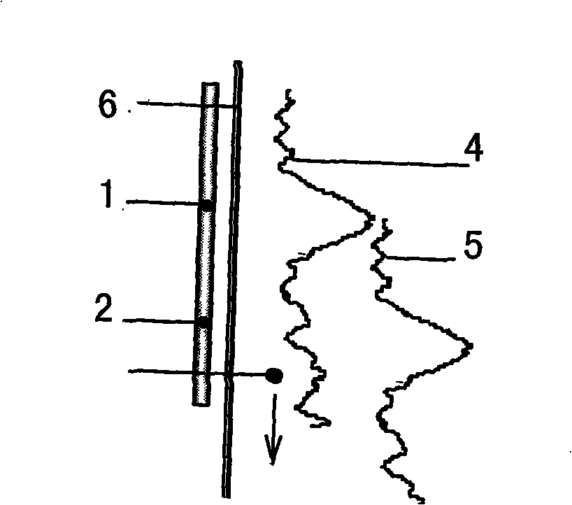
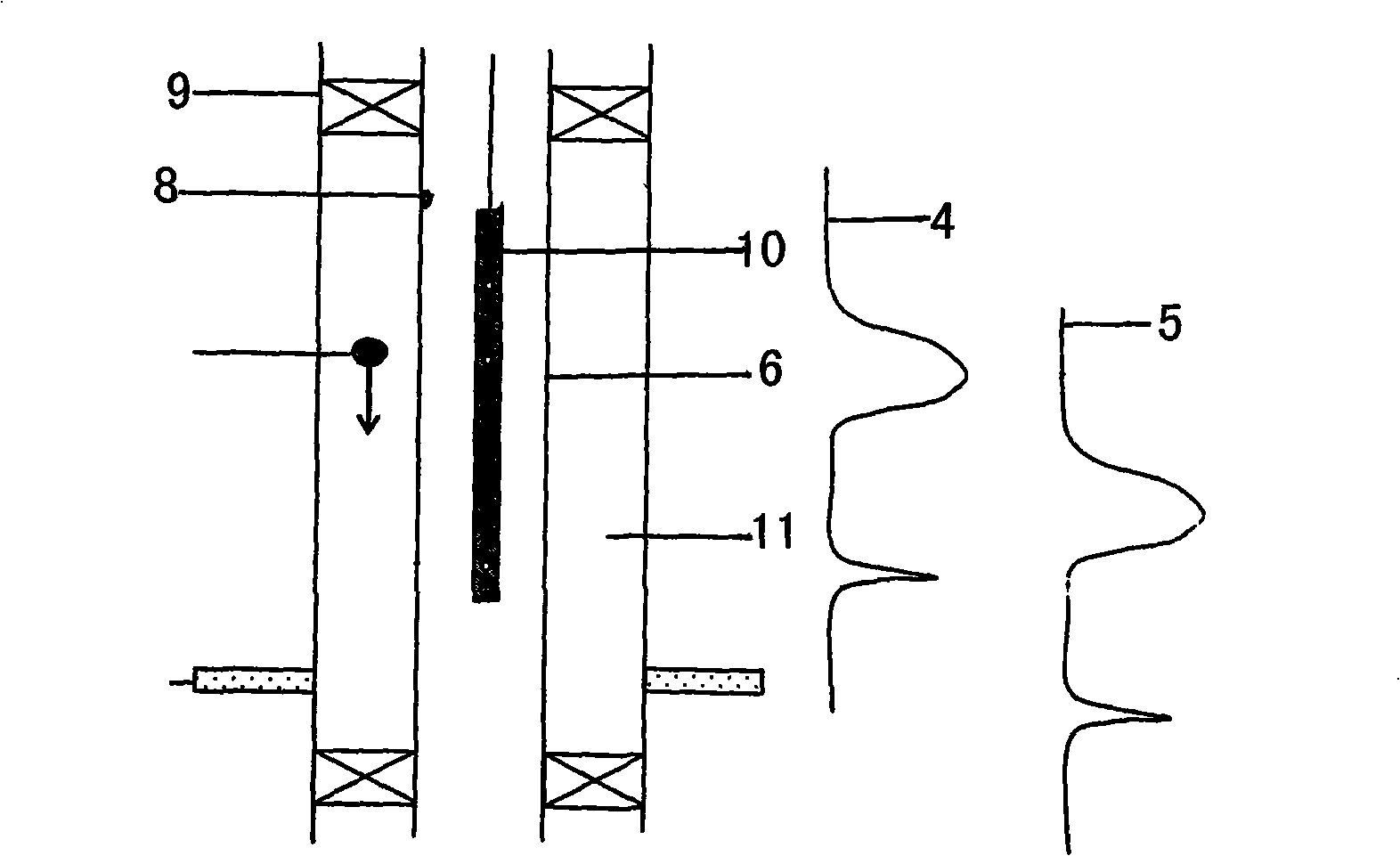
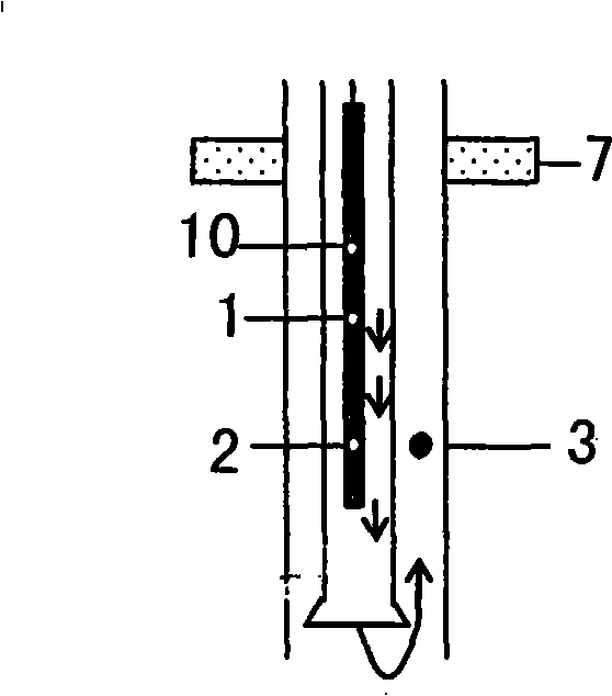
[0047] When the tracer is close to the detector, the detector will generate a corresponding output signal. If the tracer with a certain moving speed passes through two detectors with a certain distance, the two detectors will be in sequence generate respective output signals such as figure 1 shown. Due to the small distance between the two detectors,

[0048] Therefore, the output curves of the two detectors have a good similarity. It is approximately considered that the output signals of the two detectors are the same, but one of the signals is delayed by a certain time compared to the other. This delay time can be calculated by correlation Calculated by the algorithm, since the distance between the two detectors is fixed, it is easy to...


PUM


Abstract

A method is used for measuring flow injected into a section. A tracer with polymerization characteristic is released into the oil pipe of a flooding well. A part of the tracer goes through a water faucet, flows into the ring space of an oil sleeve and enters an injection layer when passing by an eccentric distributor. When the tracer is released into the oil sleeve, an instrument with two detectors should be placed at a position through which the tracer flows. When the tracer flows through two detectors in the ring space of the oil sleeve, a reciprocal change signal will be measured by the upper and the lower detectors. The other part of the tracer continues to flow down in the oil tube and the change signal is also measured by the upper and the lower detectors. Two wave crests appear on a well log. Owing to the good polymerization characteristic of the tracer, minor fluid state change combined, the small area of the ring space of the oil tube, short going-through time and the narrow width of the crest, the inner crest value of the oil tube and the crest value of the ring space of the oil sleeve can be determined. As the inner crest value of the oil tube is removed, the time when the tracer goes through the upper and the lower detectors can be worked out. Because the section of flow speed is known, the monolayer injection flow can be worked out according to an arithmetic mode.

Description

1. Technical field [0001] The invention relates to a correlation flow injection profile testing method and a construction process for layered measurement of oil field distribution injection wells by using a radioactive correlation measurement method. 2. Background technology [0002] In the field of injection profile logging, the main logging methods for measuring injection wells are turbine flowmeter, electromagnetic flowmeter, ultrasonic flowmeter, target flowmeter, isotope tracer logging and neutron oxygen activation logging. Among them, the first four logging methods are mainly used for the measurement of general injection wells (excluding the situation where there is a water-absorbing layer at the upper part of the bell mouth). At present, the most widely used of these methods is the electromagnetic flowmeter, which has a wide measurement range. Range and high measurement accuracy, the measurement lower limit can reach 1m 3 / d. The remaining three methods also have hi...

Claims


Application Information

Patent Timeline
IPC IPC(8): E21B47/10E21B47/00
Inventor 鹿洪友林建伟王优杰牟忠波徐宏
Owner 林建伟
Why Eureka
Try Eureka