Inner loop liquefaction biological reaction apparatus for wastewater treatment

A biological reaction device and sewage treatment technology, applied in the field of internal circulating fluidized biological reaction device, can solve the problems of lack of primary anaerobic treatment process, high investment and operation cost, affecting aeration effect, etc., and achieve ideal sewage purification effect. , The effect of large area and convenient operation and management

Active Publication Date: 2008-09-24
ZHEJIANG DEAN TECH
View PDF1 Cites 7 Cited by
  • Summary
  • Abstract
  • Description
  • Claims
  • Application Information

AI Technical Summary

Problems solved by technology

It overcomes the shortcomings of the existing sewage treatment equipment, which are large and complex, occupy a large area, and have high investment and operating costs, and the sewage purification effect is relatively ideal.
[0004] However, there are still certain defects in the above-mentioned patents. The above-mentioned reactor mainly only carries out the biological filler treatment process and the aerobic biochemical treatment process, and lacks the first-level anaerobic treatment process, so the purification effect is still lacking; there is also aeration in the above-mentioned reactor. The device is to aerate the entire reaction chamber. The aeration range is large, and it is not easy to form turbulence. The oxygen consumption of aeration is large, which affects the aeration effect and increases the aeration cost.

Method used


Image

  • Inner loop liquefaction biological reaction apparatus for wastewater treatment
  • Inner loop liquefaction biological reaction apparatus for wastewater treatment
  • Inner loop liquefaction biological reaction apparatus for wastewater treatment

Examples


Embodiment Construction

[0027] The present invention will be further described in detail below in conjunction with the accompanying drawings and embodiments.

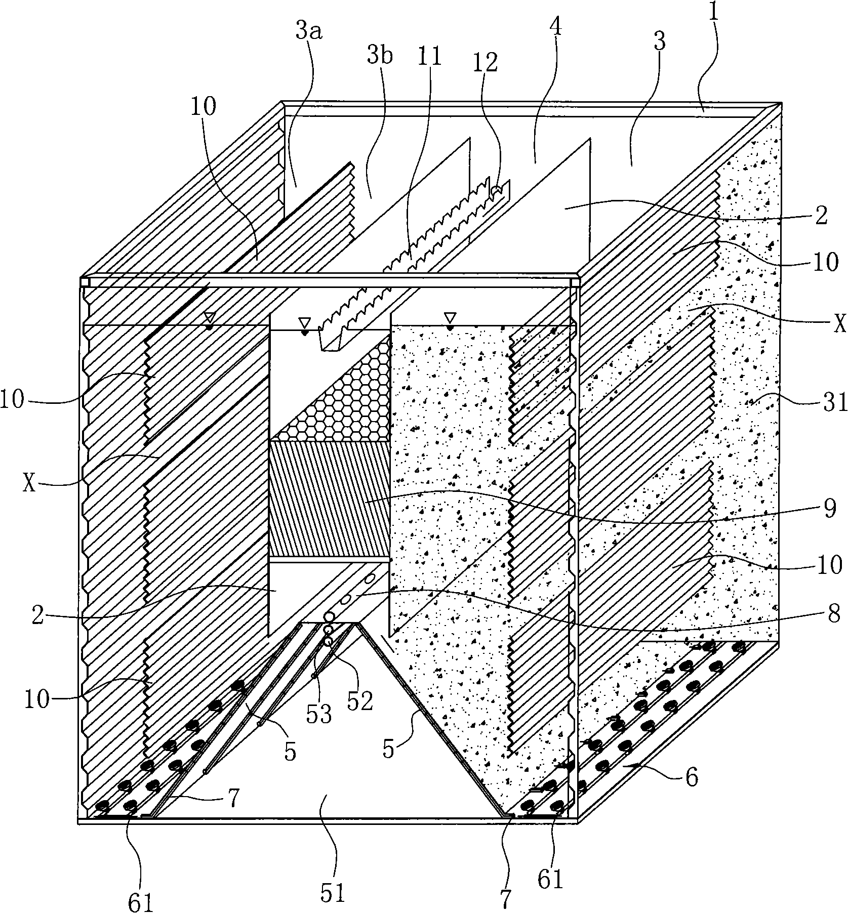
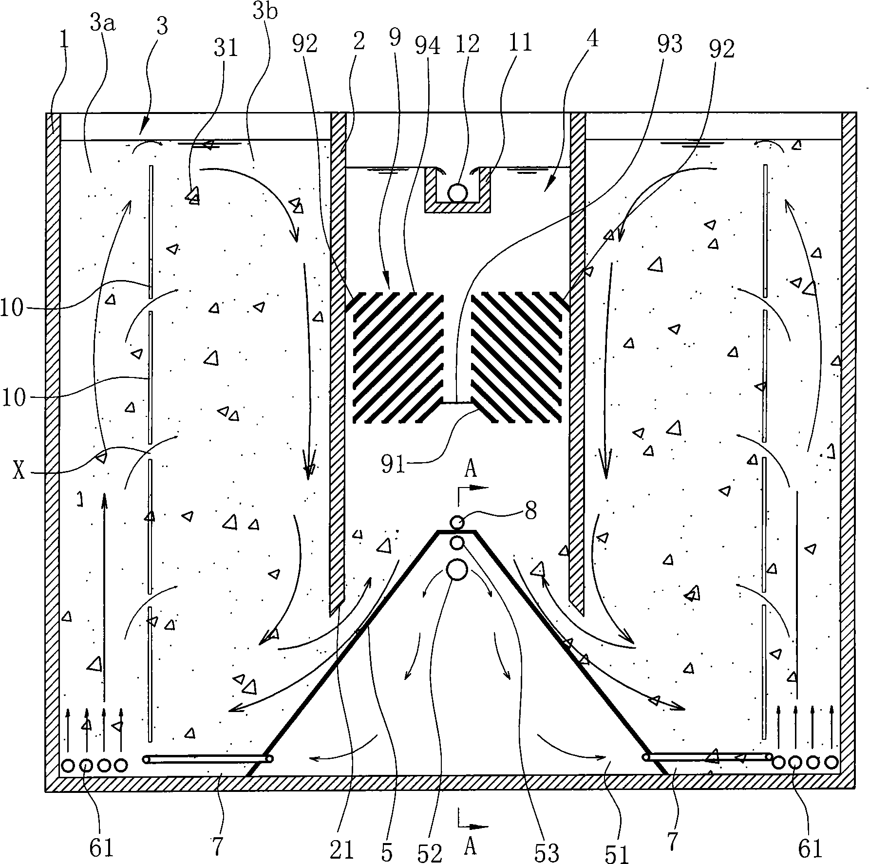
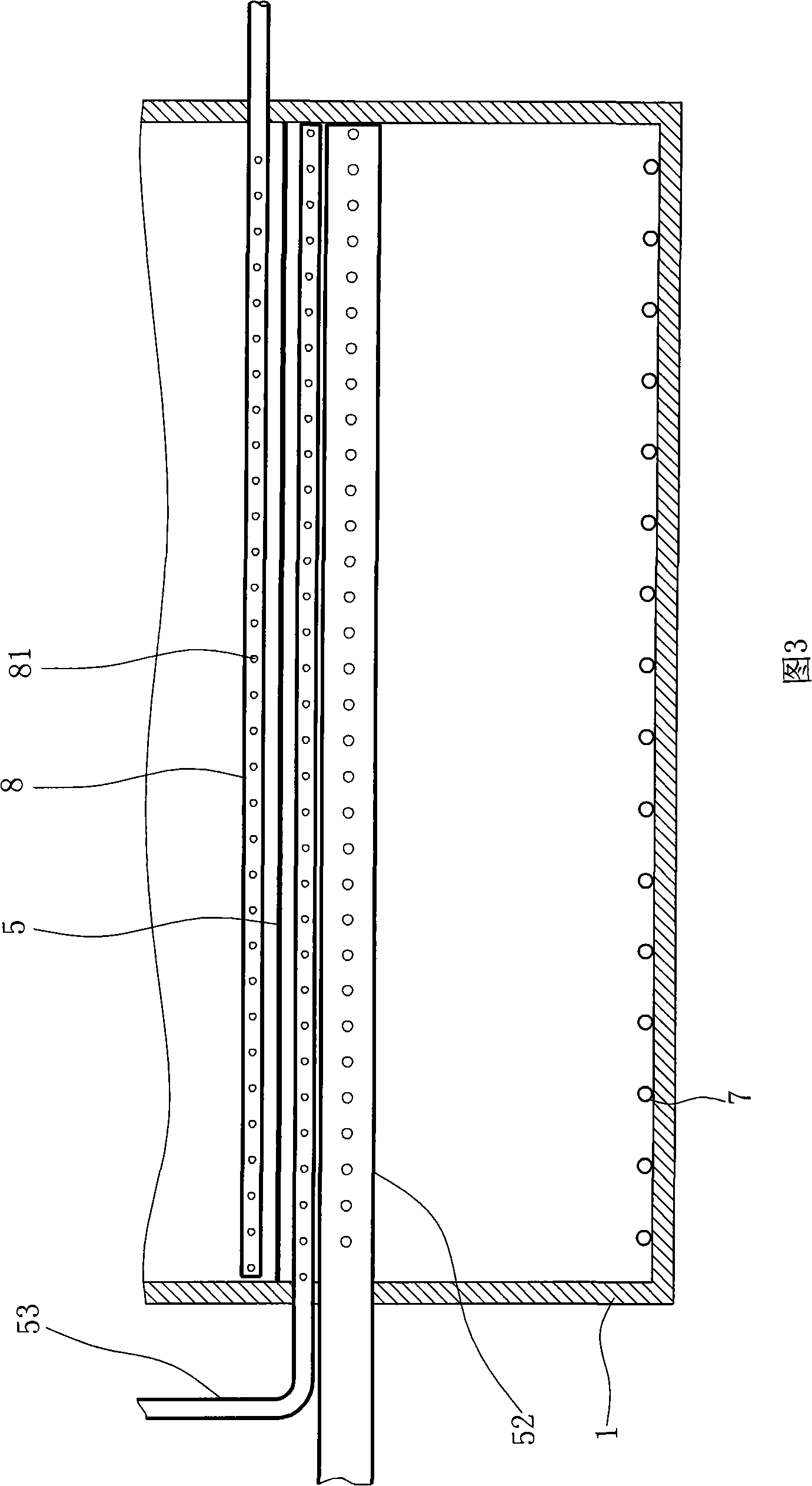
[0028] like Figure 1~6 Shown is the first embodiment of the present invention.

[0029] An internal circulating fluidized reaction device for sewage treatment, including a pool body 1, two vertical partitions 2 parallel to each other are arranged in the pool body 1, and each partition plate 2 and the pool body 1 Between the walls of the pool is a fluidized aerobic reaction zone 3, and between the two partitions 2 is a sedimentation catchment area 4, that is, the pool body 1 is provided with two fluidized wells respectively located on both sides Oxygen reaction zone 3 and a sedimentation catchment zone 4 located in the center thereof, partition plate 2 can be respectively fixed on the pool wall of the pool body 1 through its two end faces during specific implementation, thereby being fixed in the pool body 1, for Try to use the inner space o...


PUM


Abstract

The invention relates to an internal circulation fluidized bioreactor used for the sewage treatment, a pool body thereof is internally provided with a fluidized aerobic reaction zone, a settlement collecting area and an anoxic reaction zone, the bottom of the pool body is provided with an aeration device, the top part of the settlement collecting area is provided with a yielding aqueduct, the anoxic reaction zone is internally led with a water inlet pipe, the top part of the anoxic reaction zone is provided with an exhaust pipe, and the bottom of the anoxic reaction zone is provided with a water distribution pipe which communicates with the anoxic reaction zone and the fluidized aerobic reaction zone. The fluidized aerobic reaction zone is internally provided with a vertical partition board which divides the reaction zone into two zones, gaps communicated with the two zones are arranged on the partition board at intervals, and the aeration device is positioned outside the partition board. Compared with the prior art, the pool body is divided into the anoxic reaction area, the fluidized aerobic reaction zone, and the settlement collecting area, a biological reaction, a mud-water separation, and a sludge return flow systems of the sewage are combined organically, the sewage purification effect is good, the partition board divides the position of the original aerobic zone into two positions, so as to cause the aeration range to be small, the oxygen utilization ratio to be improved, and the aeration effect to be greatly increased.

Description

technical field [0001] The invention relates to the technical field of sewage treatment, in particular to an internal circulation fluidized biological reaction device for sewage treatment by using biological reactions. Background technique [0002] With the continuous shortage of water resources and the continuous strengthening of environmental pollution control, people have begun to pay attention to the treatment of various sewage and reuse it as much as possible. At present, the devices for treating urban domestic sewage can be roughly divided into activated sludge filter tanks, biological reaction filter tanks, biological contact oxidation filter towers, etc. The biological reaction filter tanks use biological fillers to fully contact sewage to produce biological reactions. , so that the sewage can be purified. Most of the current biological reaction filter tanks have defects such as large construction area, large investment, complicated operation and management, and hig...

Claims


Application Information

Patent Timeline
IPC IPC(8): C02F3/30
Inventor 俞建德
Owner ZHEJIANG DEAN TECH
Why Eureka
Try Eureka