Eureka AIR delivers breakthrough ideas for toughest innovation challenges, trusted by R&D personnel around the world.

Device for creating liquid with fine air bubbles, and device for fining air bubbles, used for the same

A technology for generating device and refiner, which is applied in chemical instruments and methods, fluid mixers, transportation and packaging, etc., can solve problems such as difficulty in carrying out, complex structure of stirring blades, etc., and achieve easy maintenance and stable liquid delivery pressure. , the effect of component simplification

Inactive Publication Date: 2008-09-17
KIKUCHI ECO EARTH
View PDF1 Cites 4 Cited by
  • Summary
  • Abstract
  • Description
  • Claims
  • Application Information

AI Technical Summary

Problems solved by technology

[0004] Patent Document 1: Japanese Patent Application Laid-Open No. 2003-117365 However, the above-mentioned existing microbubble liquid generating device is a device that intends to temporarily generate the desired microbubbles by a single gas-liquid mixing pump, so it needs to be installed on the inner periphery of the casing. A radially narrow annular fluid passage is formed, and a complex structure such as many stirring blades protruding toward the fluid passage is provided on the outer periphery of the impeller.
In addition, an inverter must be used to accurately control the speed of the gas-liquid mixing pump, which will inevitably become an expensive device.
Moreover, in order to maintain and inspect the gas-liquid mixing pump, it is necessary to be familiar with its complicated and special structure, which is not easy to do.

Method used


Image

  • Device for creating liquid with fine air bubbles, and device for fining air bubbles, used for the same
  • Device for creating liquid with fine air bubbles, and device for fining air bubbles, used for the same
  • Device for creating liquid with fine air bubbles, and device for fining air bubbles, used for the same

Examples


Embodiment Construction

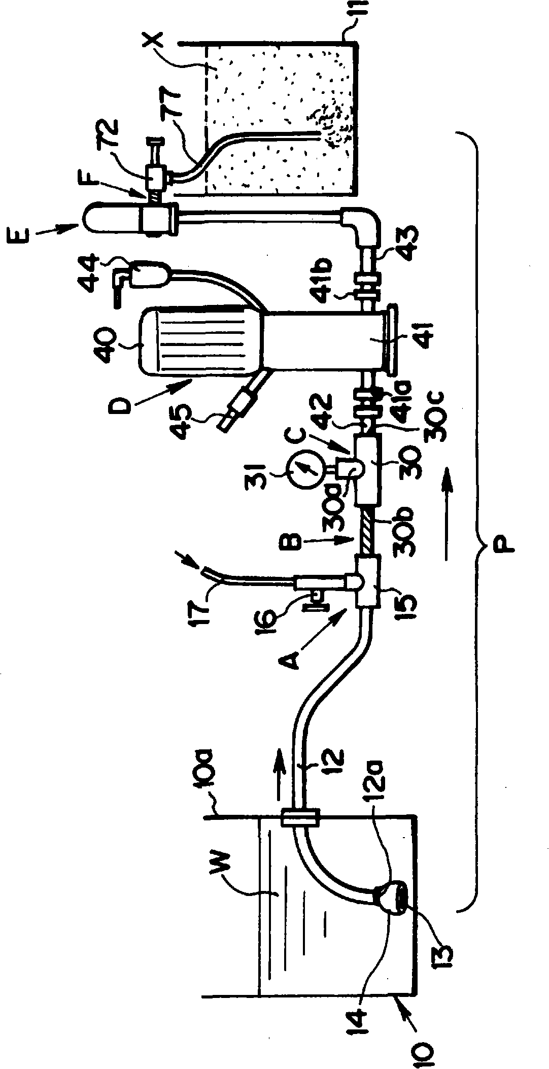
[0063] An embodiment of the present invention will be described below with reference to the drawings. figure 1 It is an overall configuration diagram of a microbubble liquid generating device according to an embodiment of the present invention.

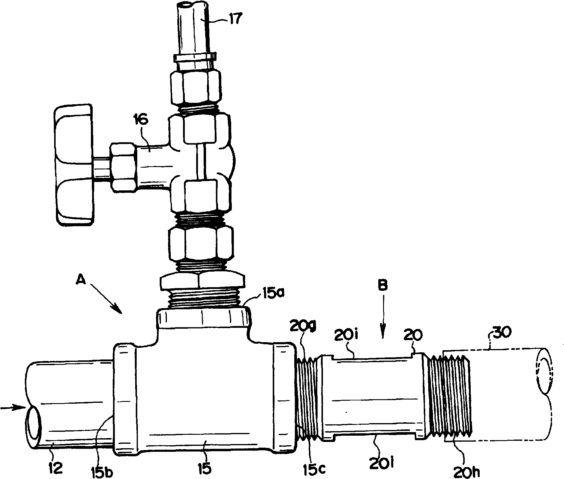
[0064] The microbubble liquid generating device according to one embodiment of the present invention is a device having a function of generating microbubble liquid containing microbubbles also called microbubbles, such as figure 1 As shown, the bubble liquid generator A, The configuration of the first bubble refiner B, the pressure measuring part C, the pressure pump D, the pressure stabilization tank E and the second bubble refiner F.

[0065] In addition, in this embodiment, water W is taken as an example of the liquid and air is given as an example of the gas, but other liquids and other gases may also be used.

[0066] The water W includes not only pure water but also natural water in rivers, ponds, lakes, and the like.

[0067...


PUM


Abstract

A device for creating a liquid with fine air bubbles, capable of efficiently creating the liquid containing sufficiently fine air bubbles and being simple and low in cost. A device for fining air bubbles, used for the apparatus, is also provided. A pressure pump (D) for sucking liquid from a liquid supply source (10) and sending the sucked liquid by pressure is provided in liquid supply pipeline (P). An air bubble liquid creater (A) for creating air bubble liquid by mixing gas into liquid by suction pressure of the pressure pump (D) is placed in the liquid supply pipeline (P), on the upstream side in a liquid supply direction of the pressure pump (D).; A first air bubble fining device (B) for fining the air bubbles contained in the air bubble liquid created by the air bubble liquid creater (A) is placed in the liquid supply pipeline (P) on the downstream side in the liquid supply direction of the air bubble liquid creator (A). A second air bubble fining device (F) for further fining the air bubbles fined by the first air bubble fining device (B) is placed in the liquid supply pipeline, on the downstream side in the first air bubble fining device (B).

Description

technical field [0001] The present invention relates to a microbubble liquid generating device and a bubble refiner used therein, for example, for separation treatment of fats and oils contained in waste liquid or treatment of excess sludge. Background technique [0002] Conventionally, as such a microbubble liquid generating device, there is, for example, a configuration disclosed in JP-A-2003-117365. [0003] Such an existing microbubble liquid generating device is characterized in that it includes a gas-liquid mixing pump for sucking a mixed fluid of liquid and gas, a resistor for applying resistance to the fluid discharged from the gas-liquid mixing pump, and a device for controlling the gas-liquid mixing pump. The rotation speed inverter forms a radially narrow annular fluid passage on the inner periphery of the casing of the gas-liquid mixing pump, and a plurality of stirring blades protruding toward the fluid passage are provided on the outer periphery of the impeller...

Claims


Application Information

Patent Timeline
Patent Type & Authority Applications(China)
IPC IPC(8): B01F3/04B01F5/06
CPCB01F3/04248B01F3/04269Y10S261/56B01F23/23121B01F23/23124
Inventor 菊池隆重石原和美
Owner KIKUCHI ECO EARTH
Why Eureka
Eureka Blog
Learn More