Cooling facility and cooling method of steel plate
A technology of cooling equipment and cooling method, which is applied in the direction of workpiece cooling device, metal processing equipment, workpiece surface treatment equipment, etc., and can solve problems such as uneven temperature, product material, adverse effects of shape, uneven cooling, etc.
- Summary
- Abstract
- Description
- Claims
- Application Information
AI Technical Summary
Problems solved by technology
Method used
Image
Examples
no. 1 approach
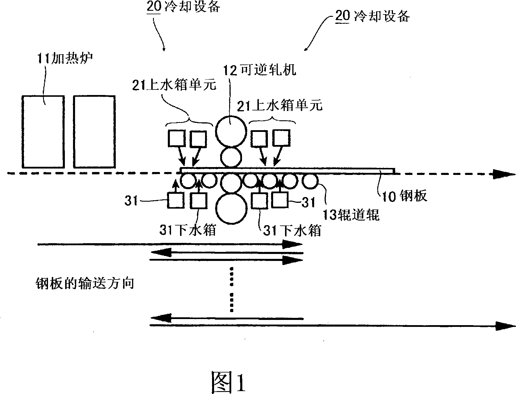
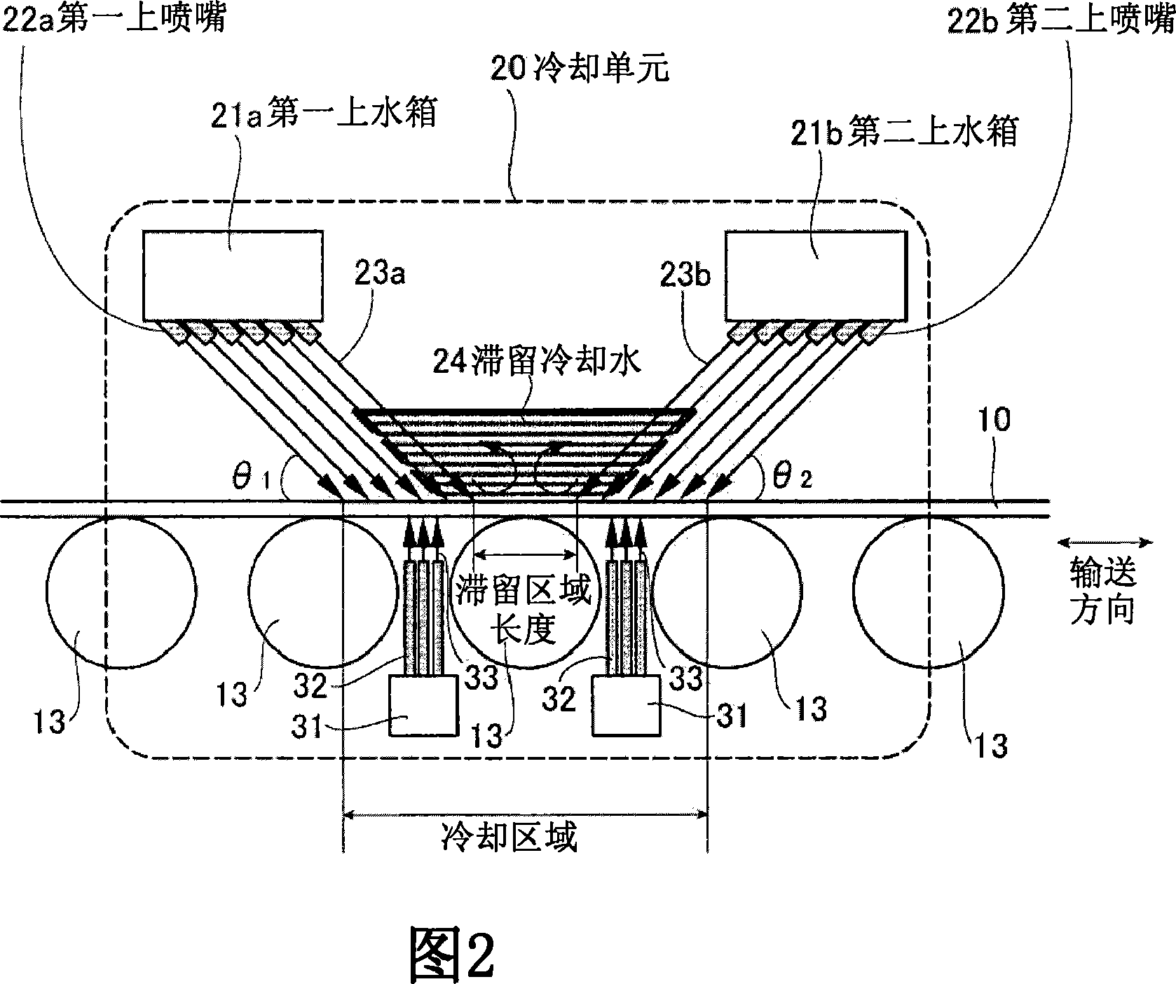
[0091] FIG. 1 is a layout diagram of a hot rolling facility for steel sheets in one embodiment of the present invention. As shown in FIG. 1 , in this embodiment, a heating furnace 11 , a reversing rolling mill 12 , and cooling equipment 20 located near the entrance (upstream side) and exit (downstream side) of the reversing rolling mill 12 are arranged. Cooling equipment (also referred to as cooling unit) 20 is a pass-through cooling equipment, as shown in Figure 2, has an upper water tank unit 21 for supplying cooling water to the upper surface of steel plate 10 and a water tank unit 21 for supplying cooling water to the lower surface of steel plate 10. The lower water tank 31 of water. Wherein, in Fig. 1 and Fig. 2, 13 is a table roller.
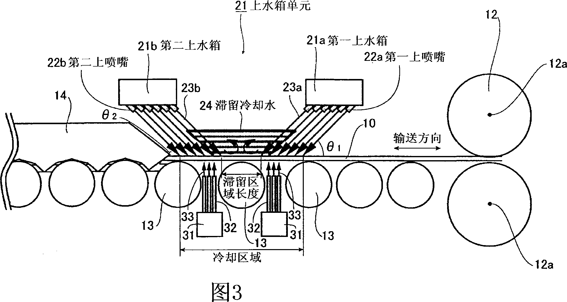
[0092] 3 and 16 are detailed views of the cooling device 20 . Wherein, in FIG. 3, the cooling device 20 is arranged between the reversing rolling mill 12 and the side guide plate 14. In FIG. 12 position. In either case, the cooling dev...
no. 2 approach
[0127] The steel plate cooling equipment in the second embodiment of the present invention, in the first embodiment shown in FIG. 0 to 35% of the steel sheet becomes a component facing outward in the width direction of the steel sheet.
[0128] As shown in FIG. 6 and FIG. 7, when the injection directions of the rod-shaped cooling water 23a and 23b are set so that 0 to 35% of the velocity components in the injection direction of the rod-shaped cooling water 23a and 23b become the velocity components toward the outside in the width direction of the steel plate, As shown by arrow A in FIGS. 6 and 7 , the cooling water sprayed from the upper nozzles 22 a and 22 b to the upper surface of the steel plate 10 merges and falls rapidly from the width end of the steel plate 10 . Therefore, compared with the case where there is no velocity component toward the outer side in the width direction of the steel sheet, the stagnant cooling water 24 can be intercepted and dewatered with a smalle...
no. 3 approach
[0141] In the above-mentioned first embodiment, when the speed of the rod-shaped cooling water 23a, 23b sprayed from the opposing upper nozzles 22a, 22b is fast, for example, 10 m / s or more, the rod-shaped cooling water 23a, 23b and the steel plate 10 After colliding, they collide with each other and fly upwards. There is no problem if the scattered cooling water falls on the stagnant cooling water 24. However, as shown in FIG. The clearance between the cooling water 23a, 23b leaks, and complete water removal cannot be performed. This problem is particularly likely to occur when the stagnation region length L is within 200 mm. In addition, when the injection speed of the cooling water is fast, the scattered cooling water 24 may fly over the header tanks 21 a and 21 b and fall onto the steel plate 10 .
[0142] In this regard, the cooling device of the third embodiment replaces the cooling unit 20 of FIG. 1 used in the first embodiment. As shown in FIG. 9, a side view is show...
PUM
 Abstract
Description
Claims
Application Information
 - Generate Ideas
- Intellectual Property
- Life Sciences
- Materials
- Tech Scout
- Unparalleled Data Quality
- Higher Quality Content
- 60% Fewer Hallucinations
Browse by: Latest US Patents, China's latest patents, Technical Efficacy Thesaurus, Application Domain, Technology Topic, Popular Technical Reports.
© 2025 PatSnap. All rights reserved.Legal|Privacy policy|Modern Slavery Act Transparency Statement|Sitemap|About US| Contact US: help@patsnap.com


