Cooling system and method for electronic components

A technology for electronic components and cooling systems, applied in electrical components, semiconductor devices of light-emitting components, cooling/heating devices of lighting devices, etc., can solve the problem of direct cooling without providing heat source, and achieve effective cooling and compact cooling system.

Inactive Publication Date: 2013-09-11
TRIDONIC JENNERSDORF GMBH
View PDF7 Cites 1 Cited by
  • Summary
  • Abstract
  • Description
  • Claims
  • Application Information

AI Technical Summary

Problems solved by technology

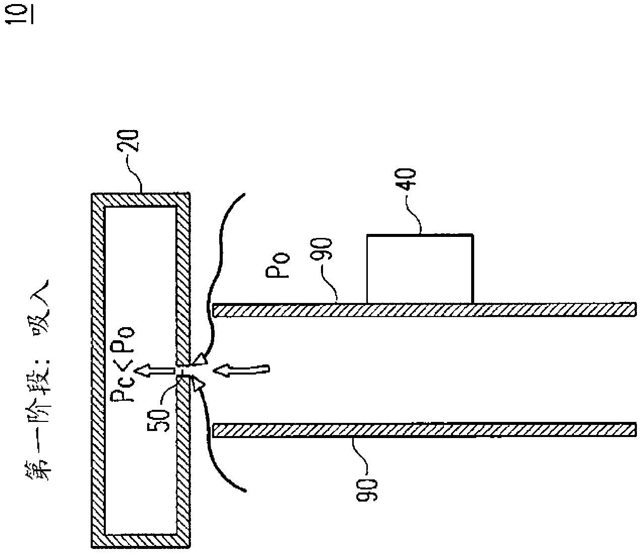
Furthermore, the heat sink 90 does not provide direct cooling of the heat source, but provides indirect cooling, and if the heat sink 90, usually made of metal, is placed on the outside of the lamp, it also presents an additional safety risk

Method used


Image

  • Cooling system and method for electronic components
  • Cooling system and method for electronic components
  • Cooling system and method for electronic components

Examples


Embodiment Construction

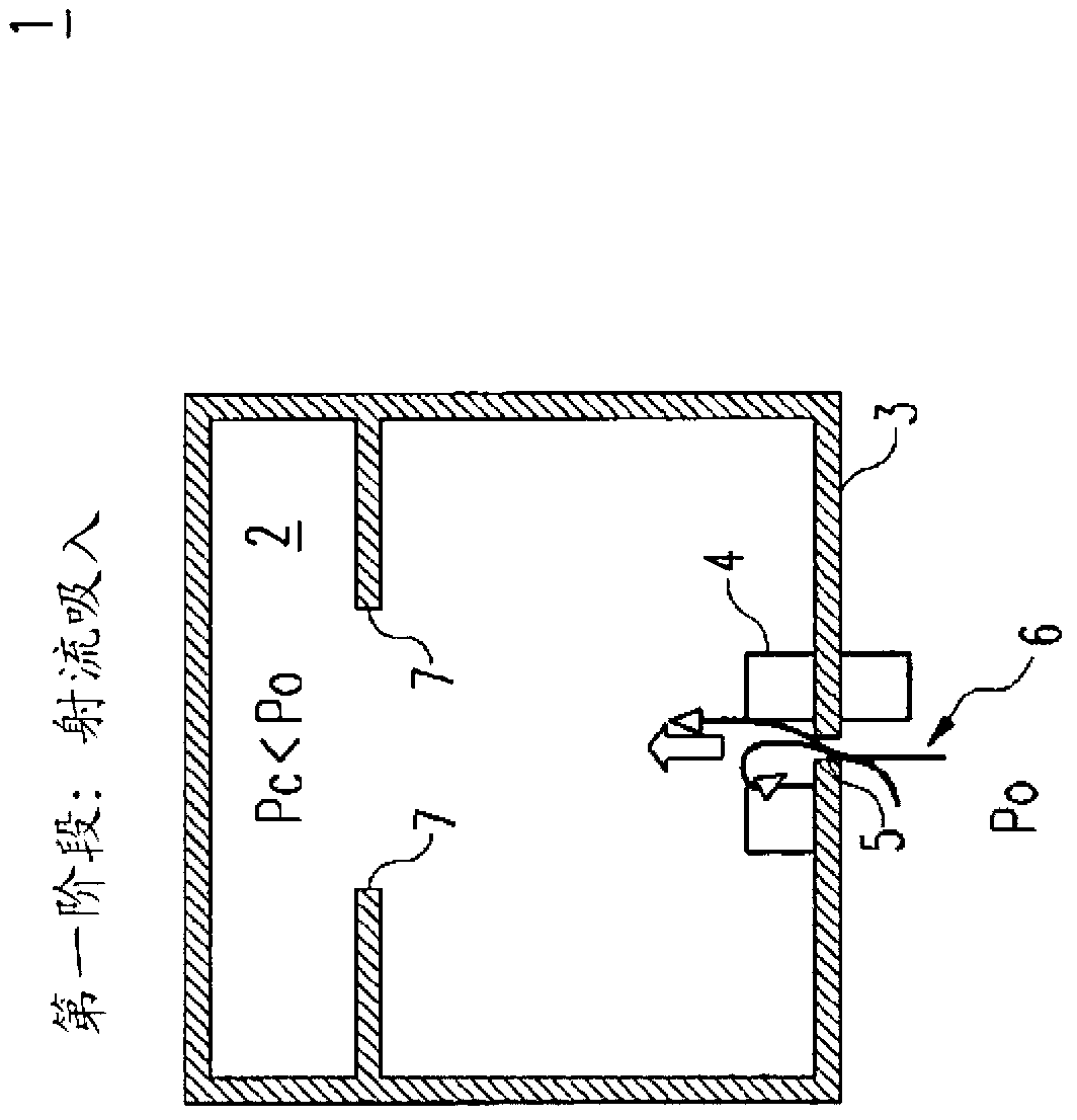
[0032] Figure 2a with 2b A cooling system 1 according to the invention is shown. The cooling system 1 comprises means for generating cyclic air pressure fluctuations, wherein the electronic components 4 are remote from the pressure generating means 7 . The pressure generating device 7 operates in two stages. Figure 2a The first stage, "Jet Inhalation", is shown. Figure 2b The second stage "jet discharge" is shown. In the first stage, the pressure generating device 7 generates a first air pressure, and in the second stage, the pressure generating device 7 generates a second air pressure, and by periodically moving from the first stage to the second stage and back to the first stage, which generates periodically varying pressures. Two-stage operation is the simplest mode of operation. However, the pressure generating device can also operate in more than two stages. The cooling system 1 also comprises means 5 which generate circulating air jets 6 when affected by the cy...


PUM


Abstract

The present invention is directed to a cooling system (1) for electronic components (4). The cooling system (1) comprises means (7) for producing cyclic air pressure fluctuations, wherein the electronic components (4) are distanced from the pressure producing means (7). In the vicinity of the electronic components (4) are situated means (5), preferably restrictions like holes, which are affected by the cyclic air pressure fluctuations, and which produce cyclic air jets (6). The air jets (6) affect the surface of the electronic component (4), and since the air jets (6) originate directly in the vicinity of the electronic components (4), an efficient heat transfer is affected. Preferably, the pressure producing means (7) actuate a pressure Pc inside a chamber (2), and turbulent air jets (6) are produced through holes (5) of a substrate (3), onto which electronic components (4) are mounted.

Description

technical field [0001] The present invention relates to cooling systems and methods for electronic components, and more particularly to cooling systems for electronic components integrated into LED lamps, especially improved LED lamps. The cooling system according to the invention works by generating cyclic air pressure fluctuations which produce cyclic air jets which affect and cool the surfaces of the electronic components. Background technique [0002] LED lights (especially modified LED lights) that include one or more light emitting diodes (LEDs) require electronic components to operate. In higher power LED lamps, the electronic components generate a lot of heat due to conversion losses. Especially in retrofit LED lamps, which operate with high intensity LEDs and are enclosed by bulbs, the heat generated is very high and can negatively affect lamp performance and lifetime. Therefore, active or forced cooling of the electronic components within such lamps is required. ...

Claims


Application Information

Patent Timeline
Patent Type & Authority Applications(China)
IPC IPC(8): F21V29/02F04F7/00F21K99/00H01L23/467F21Y101/02
CPCF04F7/00H01L23/467H01L23/4735H01L2924/0002F21V29/63F21V29/74F21V29/83F21K9/23F21K9/232F21Y2115/10H01L2924/00Y02B20/30F21V29/503H05K7/20136
Inventor 伊斯特万·巴克
Owner TRIDONIC JENNERSDORF GMBH
Why Eureka
Try Eureka