
Firedamp remote optical fiber laser detection instrument for mine

A fiber laser and detector technology, used in the measurement of color/spectral characteristics, etc., to achieve the effect of lengthening the effective absorption length and facilitating wiring

Inactive Publication Date: 2008-08-27
日照市德衡信息技术有限公司
View PDF0 Cites 23 Cited by
  • Summary
  • Abstract
  • Description
  • Claims
  • Application Information

AI Technical Summary

Problems solved by technology

[0008] This design not only uses the reference to eliminate the influence of optical path transmission, but also solves the problems of temperature drift and zero point drift in existing detection methods through continuous scanning and self-reference, and improves the anti-interference ability of the system affected by optical path loss and circuit drift.

Method used


Image

  • Firedamp remote optical fiber laser detection instrument for mine
  • Firedamp remote optical fiber laser detection instrument for mine
  • Firedamp remote optical fiber laser detection instrument for mine

Examples


Embodiment Construction

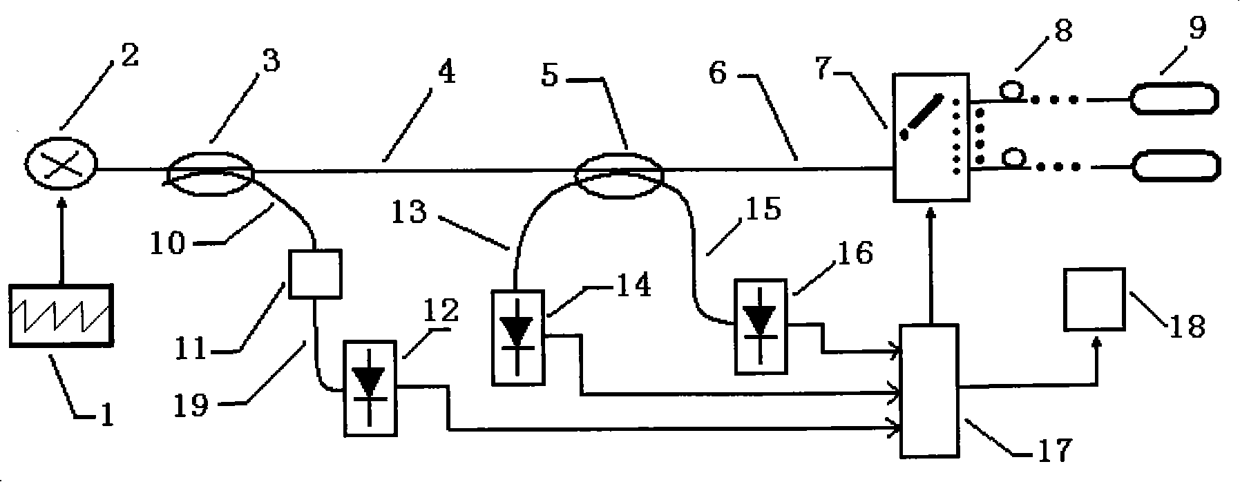
[0024] Schematic diagram of remote fiber laser detector for mine gas image 3 , which includes a distributed feedback semiconductor laser 2, a coupler, an optical switch 7, a photodetector, a data acquisition card 17, a computer 18, and the like. The distributed feedback semiconductor laser 2 is connected with the first coupler 3, the first coupler 3 is connected with the second coupler 5 through the second optical fiber 4, and the first coupler 3 is connected with the reference gas chamber 11 through the fourth optical fiber 10, from The light emitted by the reference gas chamber 11 is connected to the third photodetector 12 through the fifth optical fiber 19, and the second coupler 2 is connected to the mine optical cable 8 and the gas sensor probe 9 through the third optical fiber 6 through the optical switch 7. Connect with the first photodetector (16) through the sixth optical fiber 15, the light returned from the gas sensor probe 9 passes through the optical switch 7, th...


PUM


Abstract

The invention relates to a mine gas long-distance optical fiber laser detector, which comprises a light source and a first coupler and a second coupler which are connected with the light source, wherein, the first coupler is connected in series with the second coupler through a second optical fiber and connected with a reference gas chamber through a fourth optical fiber; light which are emitted from the reference gas chamber is connected with a third photo detector through a fifth optical fiber; one path of the second coupler is connected with a gas sensor probe through a third optical fiber; the other path of the second coupler is connected with a first photo detector through a sixth optical fiber; light which returns back from the gas sensor probe passes through the third optical fiber and the second coupler and then is connected with a second photo detector through a seventh optical fiber; the first photo detector, the second photo detector and the third photo detector are electrically connected with a data acquisition card, and electrical signals are then transmitted to a computer. The mine gas long-distance optical fiber laser detector is mainly used for coal mine gas detection.

Description

technical field [0001] The invention belongs to mine gas concentration monitoring technology, in particular to a gas remote optical fiber laser detector applied to mines. Background technique [0002] As coal is the most important primary energy in our country, the safe production of coal directly affects the national economy and people's livelihood. Methane explosion has always been one of the important disasters in coal mines, so it has been concerned by the state and society in recent years. Optical fiber gas sensor is a new type of sensor that appeared around the 1980s. The research and application of optical fiber gas sensor has appeared at home and abroad, and many methods have been experimentally applied. At present, gas detection based on optical fiber spectral absorption technology mainly includes broadband light source narrow-band filtering method, harmonic method, fluorescence method, etc. However, these methods still have some shortcomings, which restrict the pr...

Claims


Application Information

Patent Timeline
IPC IPC(8): G01N21/39
Inventor 倪家升刘统玉李艳芳赵燕杰王黔
Owner 日照市德衡信息技术有限公司
Learn More