
Optical fiber sensing method for synchronously testing temperature and pressure below horizontal well

A technology for testing optical fibers and synchronous testing, which is applied in the directions of measurement, earthwork drilling, borehole/well components, etc. It can solve the problems that the working temperature of the instrument is only suitable and cannot meet the actual needs, and achieve the effect of fast speed and large transmission capacity

Inactive Publication Date: 2008-08-27
LIAOHE GASOLINEEUM EXPLORATION BUREAU
View PDF0 Cites 3 Cited by
  • Summary
  • Abstract
  • Description
  • Claims
  • Application Information

AI Technical Summary

Problems solved by technology

[0002] At present, the downhole testing in the field of oil exploitation technology at home and abroad mainly adopts the downhole recording method of mechanical sensing, and relies on the gravity downhole and vertical movement recording test methods. Since the above-mentioned device is only suitable for oil wells with a vertical angle of less than 10 degrees during testing, in addition Although the electronic sensor ground recorder can be tested in wells with large angles, the operating temperature of this type of instrument is only suitable for oil wells within 260 °C. With the development of oil fields, some highly deviated and horizontal wells appear due to the limitation of well depth. The above method for testing can no longer meet the actual needs

Method used


Image

  • Optical fiber sensing method for synchronously testing temperature and pressure below horizontal well
  • Optical fiber sensing method for synchronously testing temperature and pressure below horizontal well
  • Optical fiber sensing method for synchronously testing temperature and pressure below horizontal well

Examples


Embodiment Construction

[0016] The present invention is provided by the following embodiments, which will be described below in conjunction with the accompanying drawings:

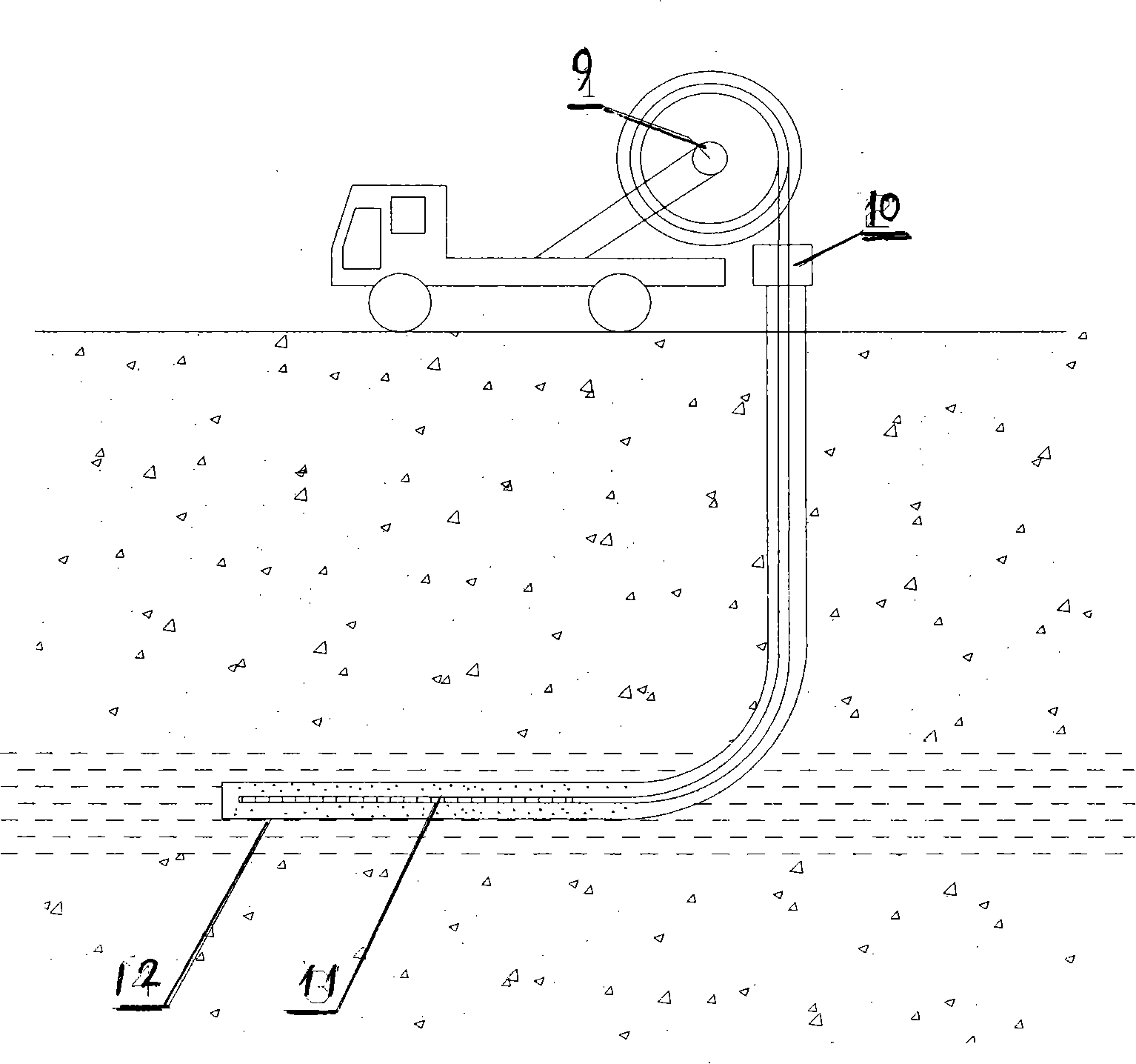
[0017] exist figure 2 In the test method, the high temperature and high pressure test optical fiber 11 is lowered into the perforated section 12 of the oil layer in the horizontal well with the high temperature and high pressure test wellhead sealer 10 by using the special optical cable equipment 9 to perform temperature and pressure tests.

[0018] exist figure 1 Among them, the test optical fiber 11 is composed of the core 4 in the outer shell 2, the outer shell is a hollow tube made of 1cr18ni9ti, stainless steel material, and the core 4 in the circular tube has a certain length. Thin wires made of germanium, boron, and silicon dioxide are provided with ultraviolet gratings 6 parallel to each other on equal sections of thin wire cross sections, and polyene argon ammonia is installed in the annular chamber between the shell l...


PUM


Abstract

The invention relates to a horizontal underground temperature and pressure synchronous test optical fiber sensing method which belongs to the thick oil heat extraction and horizontal section profile temperature and pressure synchronous test field. The invention performs temperature and pressure test by using optical cable special equipment to run a test optical fiber into a perforation section of a horizontal well oil layer provided with a sealer. The method is not limited by direction and angle during the test process; temperature and pressure balance is not affected, test precision and transmission effect are not affected by a wellbore, and simultaneous identification of horizontal section temperature and pressure can be realized; moreover, the optical fiber and optical fiber equipment used have the advantages of large transmission capacity, quick speed, strong electromagnetic resistance and geomagnetic resistance, and capability of directly reading and storing test parameters on the ground.

Description

Technical field: [0001] The invention relates to an optical fiber sensing method for synchronously testing the temperature and pressure in a horizontal downhole, belonging to the field of synchronizing the temperature and pressure of a horizontal well section during thermal exploitation of heavy oil. Background technique: [0002] At present, the downhole testing in the field of oil exploitation technology at home and abroad mainly adopts the downhole recording method of mechanical sensing, and relies on the gravity downhole and vertical movement recording test methods. Since the above-mentioned device is only suitable for oil wells with a vertical angle of less than 10 degrees during testing, in addition Although the electronic sensor ground recorder can be tested in wells with large angles, the operating temperature of this type of instrument is only suitable for oil wells within 260 °C. With the development of oil fields, some highly deviated and horizontal wells appear du...

Claims


Application Information

Patent Timeline
IPC IPC(8): E21B47/06
Inventor 马明杨天佑宋启辉刘付臣曾魏黄昌义张涛王风岩
Owner LIAOHE GASOLINEEUM EXPLORATION BUREAU
Learn More