Radio reception system that can remove interference signal component
a radio reception system and interference signal technology, applied in the field of radio reception systems, can solve the problems of not being able to extract only the signal the conventional adaptive array b>11/b> cannot separate the signals of users b>1/b> and b>3/b>, so as to improve communication quality, improve communication quality, and improve communication quality
- Summary
- Abstract
- Description
- Claims
- Application Information
AI Technical Summary
Benefits of technology
Problems solved by technology
Method used
Image
Examples
second embodiment
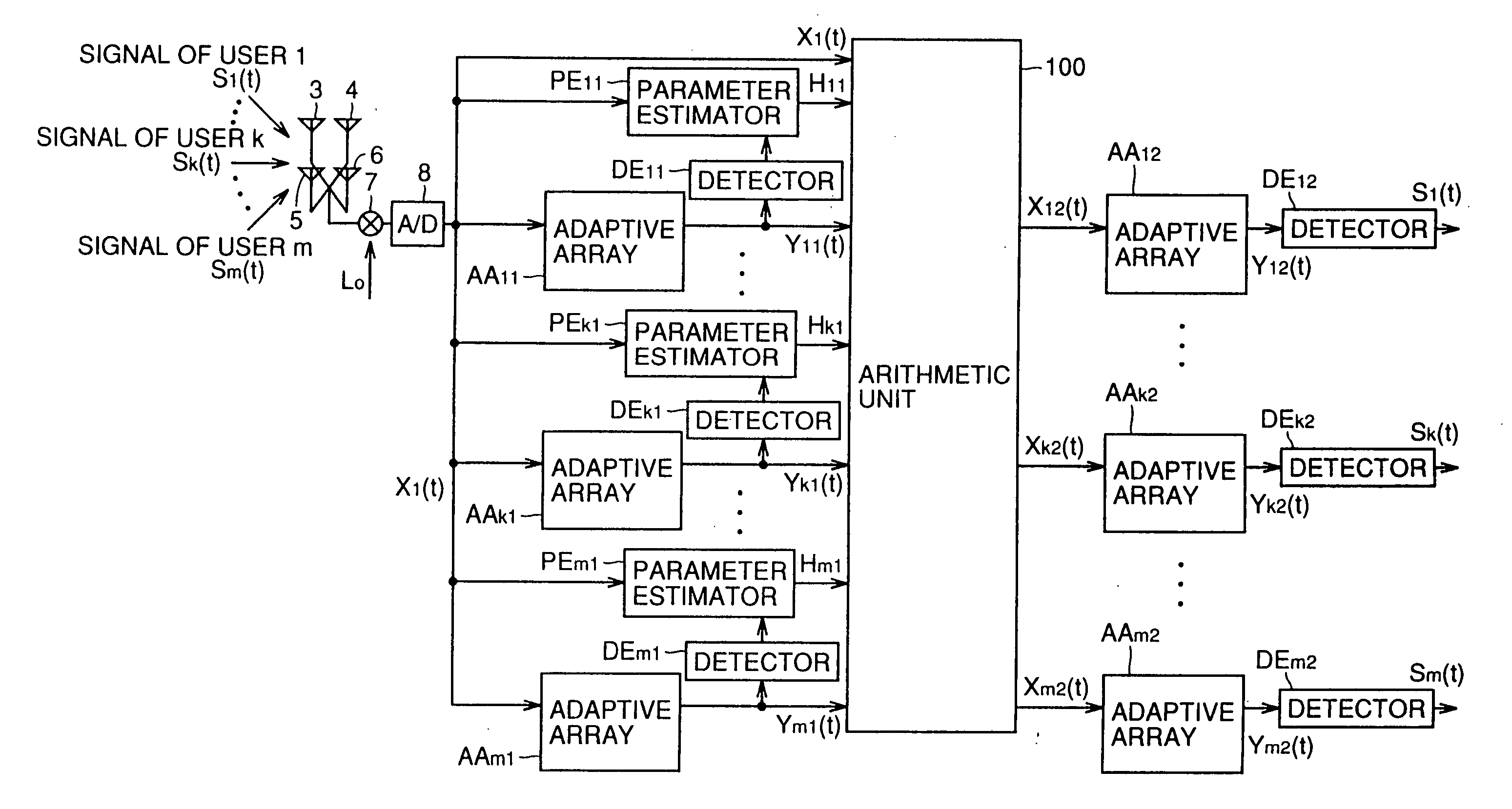
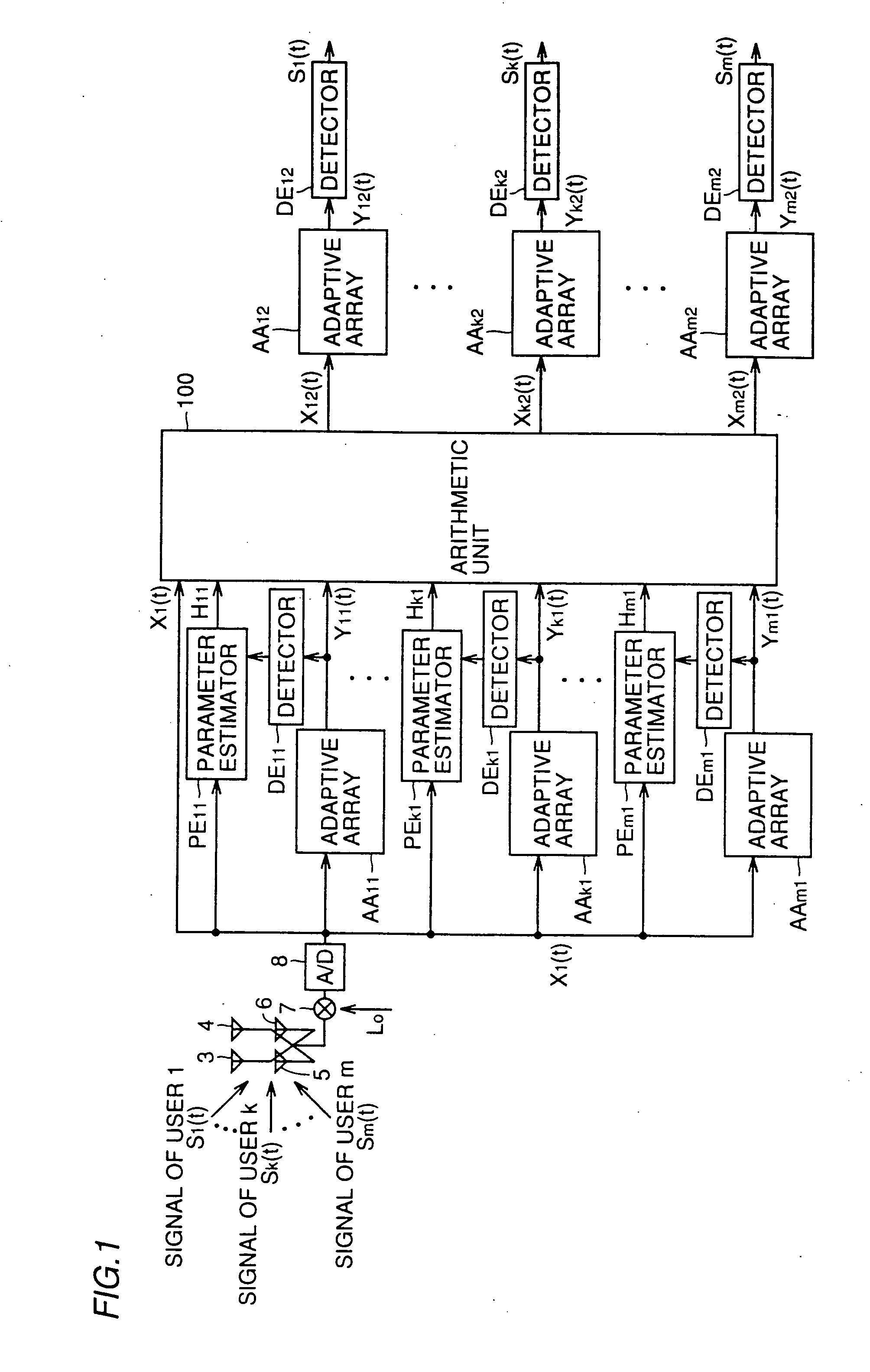
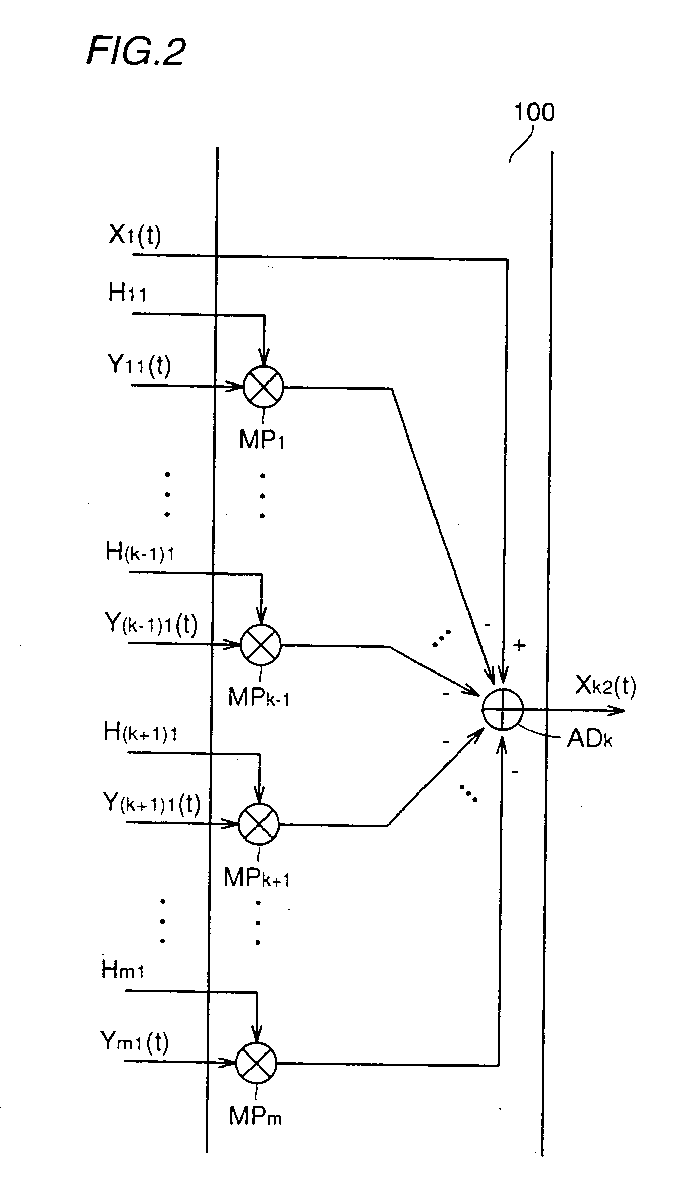
[0068]FIG. 3 is a block diagram showing the present invention. The embodiment of FIG. 3 further improves the property by providing in series a plurality of stages of user detection device, as well as detectors, each stage being formed of the adaptive arrays, the parameter estimators, and the arithmetic unit of FIG. 1 to reduce in a step-manner the ratio of the signal component of other users included in the user signal output from each stage. The operation of the circuit of each stage has been already described in detail with reference to FIGS. 1 and 2, and will not be repeated here.
third embodiment
[0069]FIG. 4 is a block diagram showing the present invention.
[0070] Referring to FIG. 4, input signal vector X1 (t) output from A / D converter 8 is applied to adaptive arrays AAl1, . . . , AAk1, . . . , AAm1 and to arithmetic unit 201. Adaptive arrays AAl1, . . . , AAk1, . . . , AAm1 extract and provide to arithmetic unit 201 corresponding user signals Yl1 (t), . . . , Yk1 (t), . . . , Ym1 (t), respectively.
[0071]FIG. 5 is a specific block diagram of arithmetic unit 201 of FIG. 4. In FIG. 5, only the portion that carries out a signal process corresponding to user k is depicted out of the entire structure of arithmetic unit 201 for the sake of simplifying the description. The circuit of the same structure is provided corresponding to each of users 1, . . . , k−1, k+1, . . . , m besides user k.
[0072] The structure to generate input signal vector Xk2 (t) corresponding to user k will be described hereinafter with reference to FIG. 5. Arithmetic unit 201 includes parameter estimators P...
sixth embodiment
[0099] In the present sixth embodiment, a signal Sk+1 (t) of a more correct level of user k+1 can be extracted by using the signal vector obtained by multiplying the detected signal Yk (t) of user k by reception signal coefficient vector Hk output from the parameter estimator and subtracting the multiplied value from input signal vector Xk (t) used in the user detection device of the k-th stage, as input signal vector Xk+1 (t) of adaptive array AA(k+1)1 of the user detection device of the (k+1)th stage.
[0100]FIG. 9 is a diagram to describe the operation of the parameter estimator used in each of the above embodiments. In a reception system with n antenna elements and m users connected in path multiplex, input signal vector Xk (t) of the k-th parameter estimator PEk1 connected in parallel is represented by the following equation (21).
Xk (t)[x1k (t), x2k (t), . . . , xnk (t)]T (21)
xjk (t)=hjkSk (t)+hjk+1Sk+1 (t)+ . . . +hjmSm (t)+
nj (t), (k=1, 2, . . . , n) (22)
[0101] A vector re...
PUM
 Abstract
Description
Claims
Application Information
 - R&D
- Intellectual Property
- Life Sciences
- Materials
- Tech Scout
- Unparalleled Data Quality
- Higher Quality Content
- 60% Fewer Hallucinations
Browse by: Latest US Patents, China's latest patents, Technical Efficacy Thesaurus, Application Domain, Technology Topic, Popular Technical Reports.
© 2025 PatSnap. All rights reserved.Legal|Privacy policy|Modern Slavery Act Transparency Statement|Sitemap|About US| Contact US: help@patsnap.com


