
Single-crystal electromagnetic field

An electromagnetic field and single crystal technology, applied in the field of electromagnetic field, can solve problems such as difficulty in forming a strong magnetic field, complicated manufacturing process, and temperature influence, and achieve the effects of stable magnetic field, good heat transfer, and improved symmetry

Active Publication Date: 2008-08-20
LONGI MAGNET CO LTD
View PDF0 Cites 3 Cited by
  • Summary
  • Abstract
  • Description
  • Claims
  • Application Information

AI Technical Summary

Problems solved by technology

In foreign countries, the longitudinal magnetic field is used in the test, that is, the magnetic field is along the crystal rising direction, and the high magnetic field strength will affect the product performance. In actual use, the furnace and the magnetic field are designed at the same time. The furnace and the magnetic field are integrated, but there is no See products coming out
This kind of magnetic field integrated with the furnace has the following disadvantages: 1. Limited by space; 2. Influenced by temperature; 3. It is difficult to form a strong magnetic field; 4. The manufacturing process is very complicated

Method used


Image

  • Single-crystal electromagnetic field
  • Single-crystal electromagnetic field
  • Single-crystal electromagnetic field

Examples


Embodiment Construction

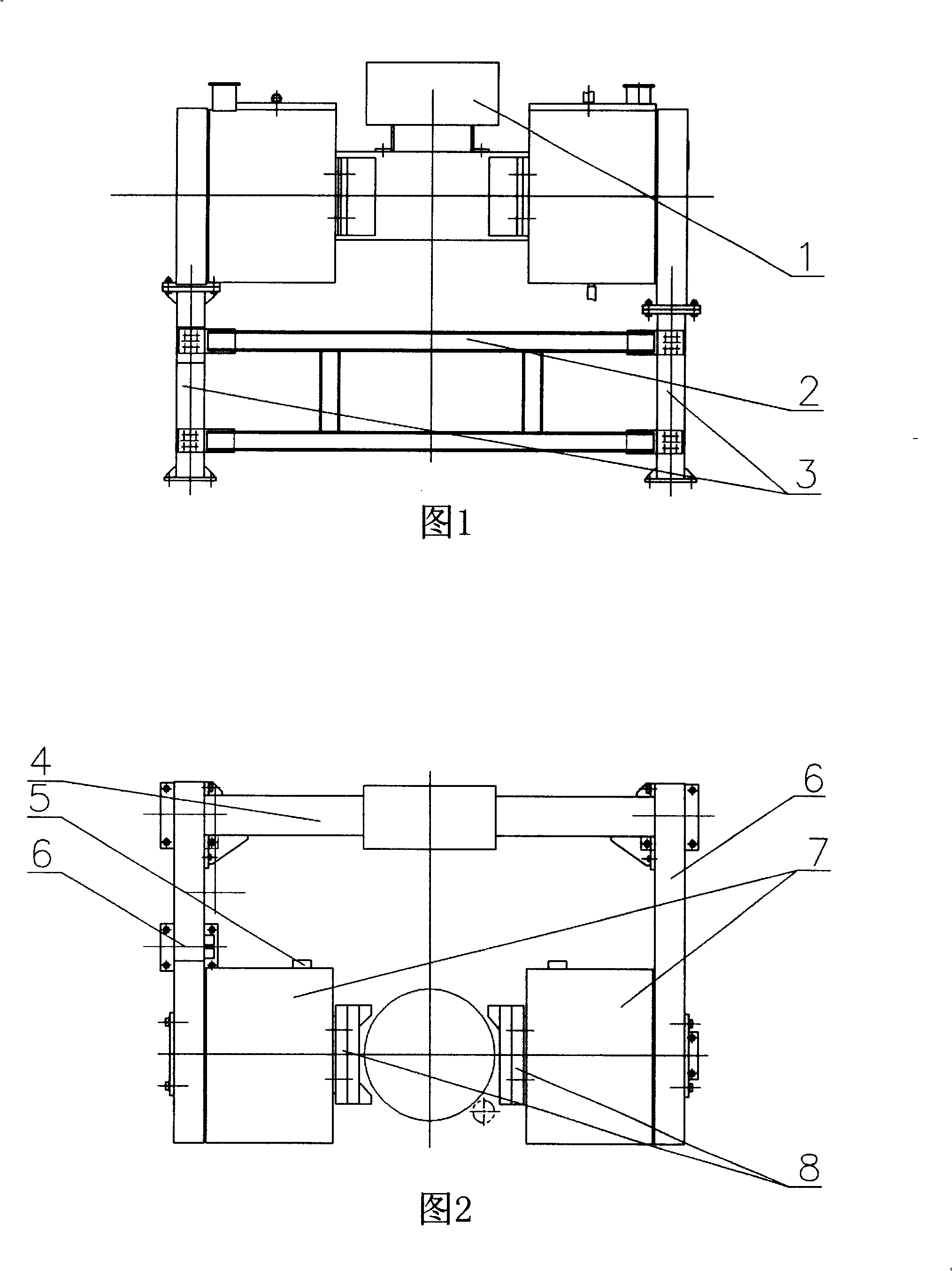
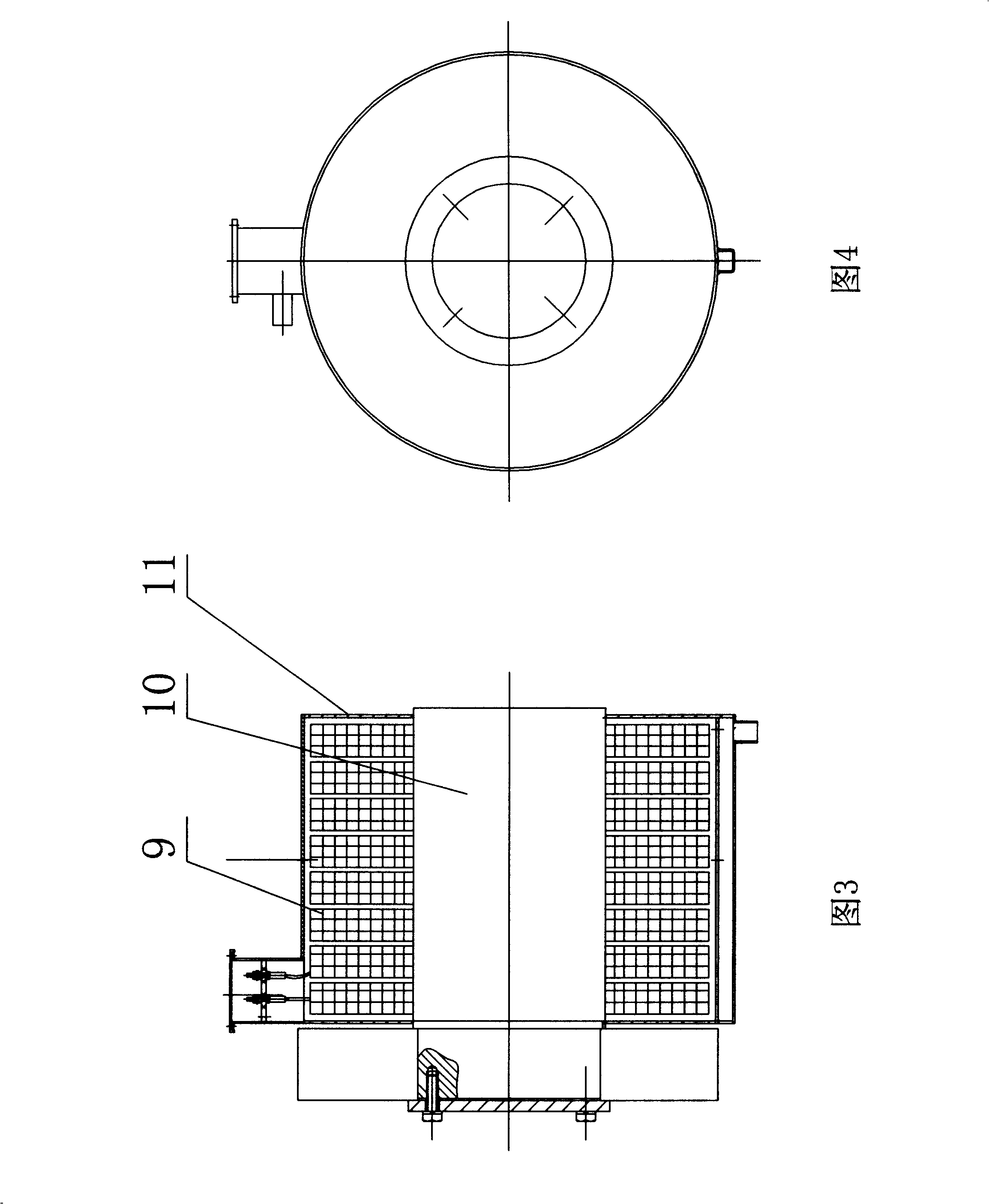
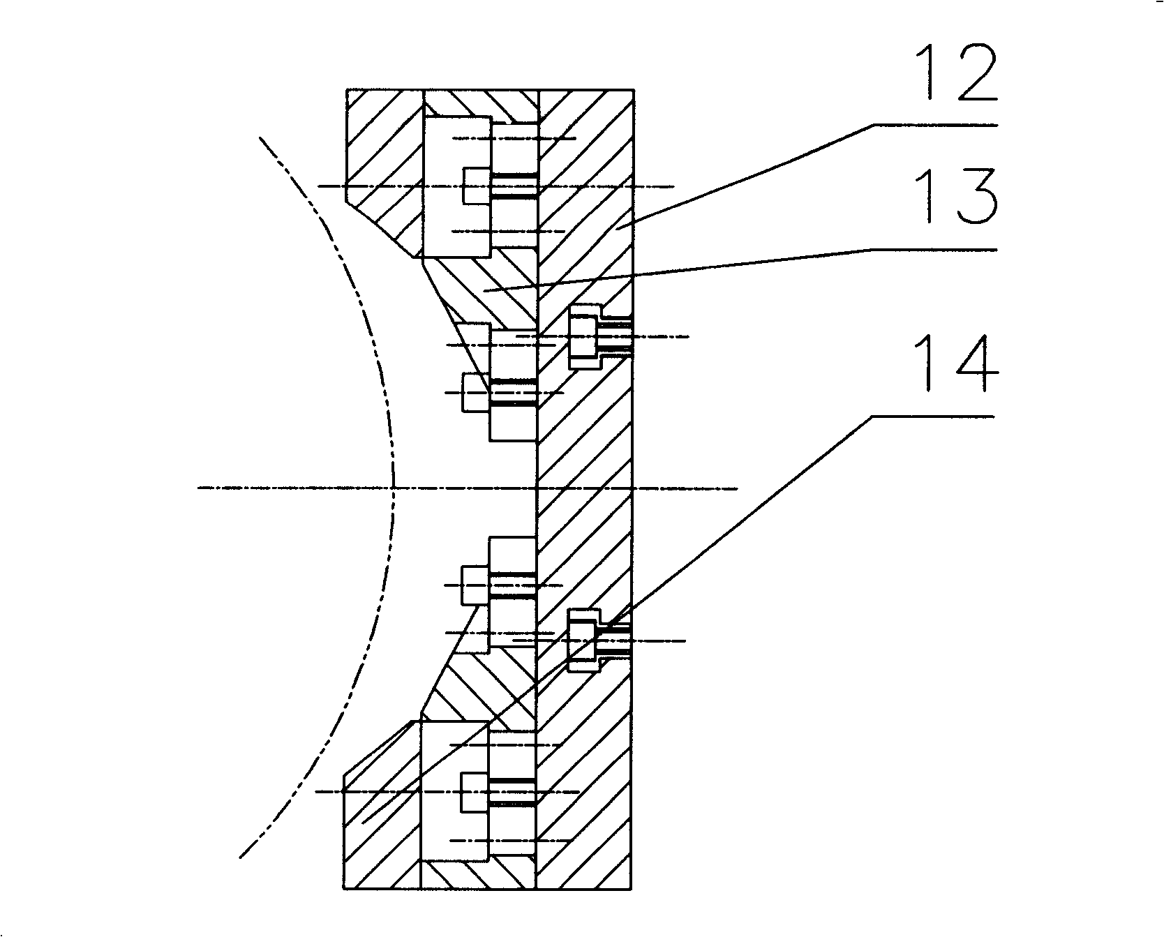
[0014] The single crystal electromagnetic field is composed of a yoke plate 6, a magnetic plate 4, a magnetic pole 7 and a pole head 8. One end of the two yoke plates 6 is connected through the magnetic plate 4, and the other end of the yoke plate 6 is connected to the magnetic pole 7. The two magnetic poles 7 correspond to each other. There are pole heads 8 on the opposite surfaces of the two magnetic poles 7 , wherein the connection between the magnetic poles 7 and the yoke plate 6 and between the yoke plate 6 and the magnetic conductive plate 4 is bolted. Two yoke plates 6 , magnetic guide plates 4 and two magnetic poles 7 form a C-shaped frame, and the two yoke plates 6 are respectively connected with two columns 3 by bolts, and a connecting beam 2 is fixed between the two columns 3 with bolts. A cooling system 1 is connected to the magnetically conductive plate 4 .

[0015] The magnetic pole 7 is composed of a coil 9 , an iron core 10 and a casing 11 . The magnetic pole ...


PUM


Abstract

The invention discloses a mono-crystal electromagnetic field for being matched with a mono-crystal furnace in the production of semiconducting material, which consists of yoke plates, a concentrating flux plate, magnetic poles and pole heads. One end of each yoke plate is connected with each other by the concentrating flux plate and the other end thereof is connected with the magnetic poles; two magnetic poles are corresponding to each other and the corresponding face of the two magnetic poles is provided with the pole heads; the two yoke plates, the concentrating flux plate and the two magnetic poles form a C-shaped frame; the two yoke plates are respectively fixed on two columns that are connected by a connecting beam; the concentrating flux plate is connected with a cooling system. The mono-crystal electromagnetic field is stable and adjustable, can promote material utilization rate and the property index of a silicon chip and can improve the utilization rate of the material and the performance index of silicon chip. The mono-crystal electromagnetic field can change the exiting mono-crystal furnace to achieve the requirement for improving the quality of monocrystal, can design according to mono-crystal furnaces with different structures to satisfy the requirements of different users and has comparatively simple structure and lower production cost.

Description

1. Technical field [0001] The invention belongs to single crystal silicon production equipment in the semiconductor material industry, and in particular relates to an electromagnetic field matched with a single crystal furnace. 2. Background technology [0002] The production of conventional semiconductor material silicon crystal is to melt the polycrystalline block into liquid in the single crystal furnace and then pull out the single crystal rod. Due to the influence of temperature, the temperature of the upper part of the silicon liquid is low, and the temperature of the bottom is high, which naturally forms a circulation, and the whole liquid is in a tumbling state. The conductive medium added to the silicon liquid is unevenly distributed. The radial distribution on the surface is uneven, resulting in a large difference in resistivity, and the resistivity of the head and tail of the ingot is not the same. When the user needs a wafer with a certain resistance range, only...

Claims


Application Information

Patent Timeline
Patent Type & Authority Applications(China)
IPC IPC(8): C30B15/00
Inventor 张承臣李恒盛吴文奎胡占林李朝朋邵贵成
Owner LONGI MAGNET CO LTD
Learn More