Engine cover
An engine cover and circular technology, which is applied to the upper structure, springs, upper structure sub-assembly, etc., can solve the problems of rubber shock absorber falling off and unstable posture of rubber shock absorber, so as to improve the ease of assembly and maintain Posture stability and the effect of drop-off resistance
- Summary
- Abstract
- Description
- Claims
- Application Information
AI Technical Summary
Problems solved by technology
Method used
Image

Examples
Embodiment approach 1
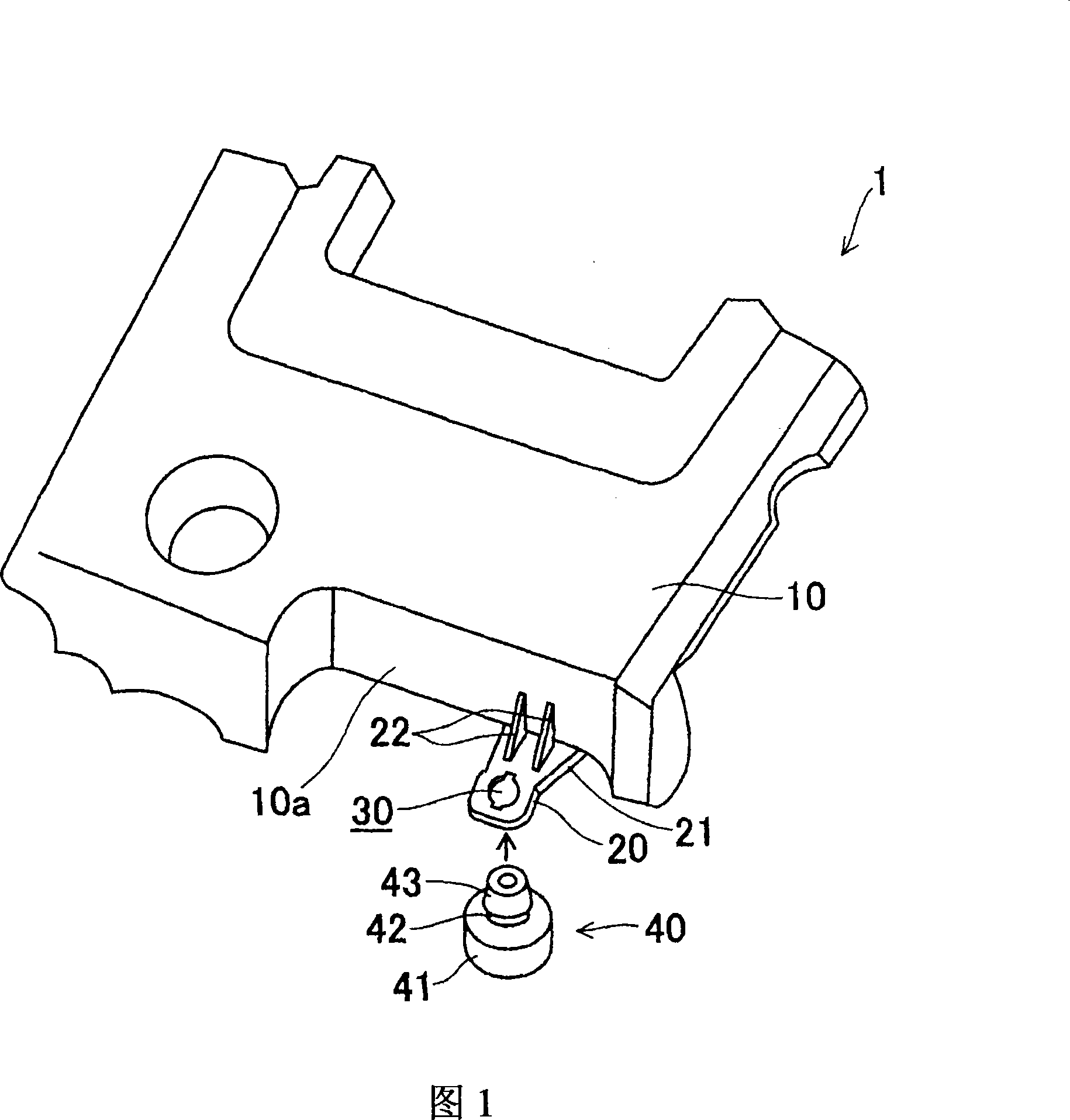
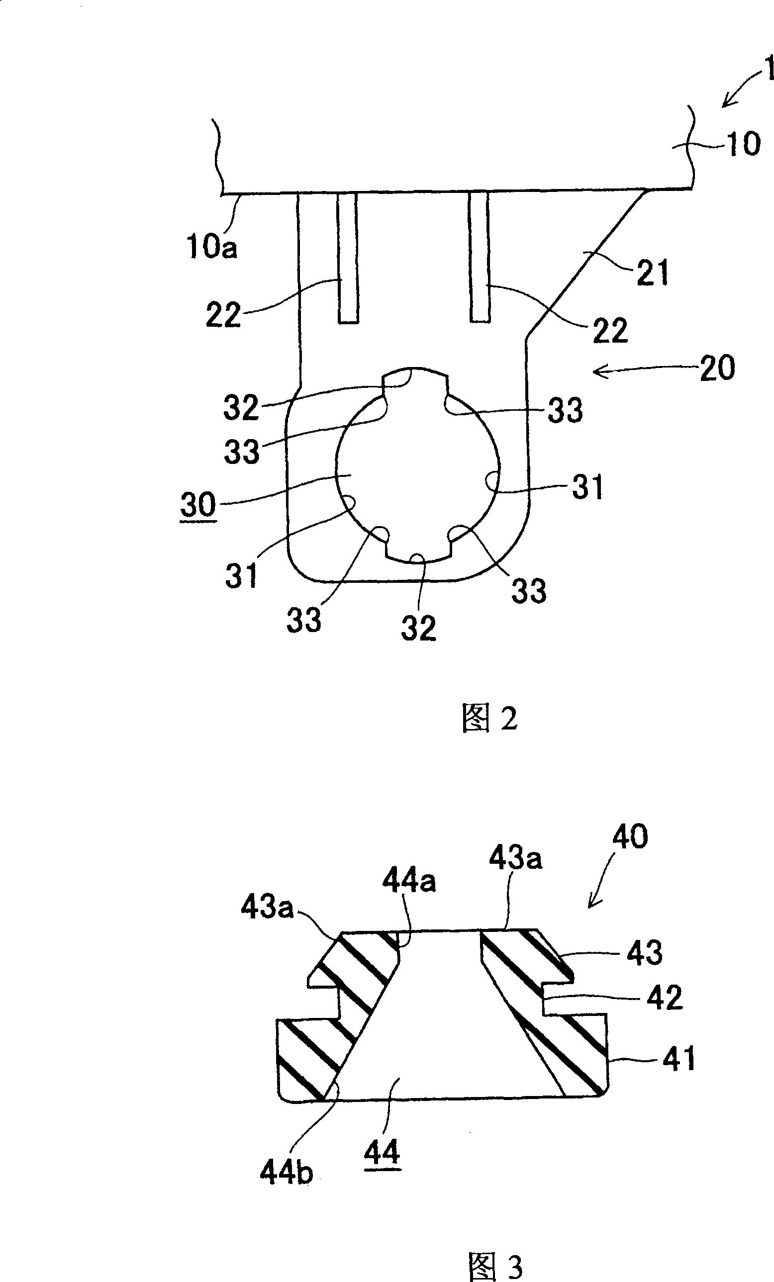
[0039]The engine cover 1 according to the present embodiment shown in FIGS. 1 to 4 has: a cover main body portion 1; a mounting seat plate portion 20 integrally provided on the cover main body portion 10; and three mounting seats (not shown). As shown in the figure), they are integrally provided on the cover main body 10. The cover main body portion 10, the mounting seat plate portion 20, and the three mounting seats are integrally formed by injection molding of synthetic resin such as PP (polypropylene) or PA (nylon).
[0040] As shown in FIG. 1 , the cover body 10 has a substantially quadrangular tray shape. On the cover main body 10 , a mounting seat plate portion 20 is provided near one of the four corners, and mounting seats (not shown) are arranged at the other three positions of the four corners. In addition, three mounts are integrally provided on the rear surface of the cover main body 10 .
[0041] The mounting seat plate portion 20 is provided in a cantilever shap...
Embodiment approach 2
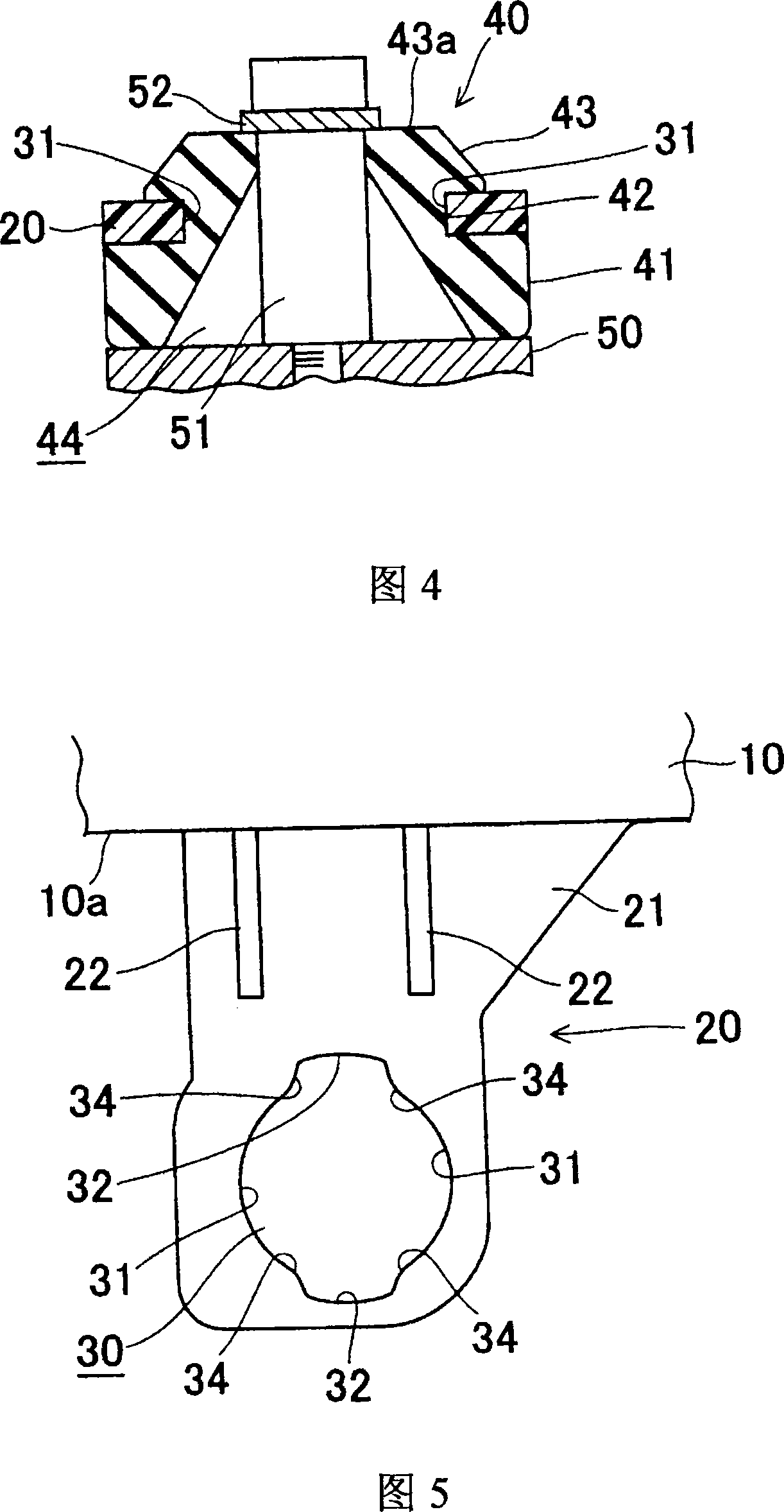
[0060] In this embodiment shown in FIG. 5 , the shape of the circular mounting hole 30 is changed.
[0061] That is, the circular mounting hole 30 on the engine cover 1 according to the present embodiment has, as in the first embodiment described above, a pair of arc-shaped fitting recesses 31, 31 which face each other in the radial direction; The relief recesses 32, 32 are radially opposite. In addition, at the boundary between each arc-shaped fitting recessed portion 31 and each relief recessed portion 32 , instead of the aforementioned corner portion 33 , a curved surface portion 34 is formed, respectively.
[0062] Thus, if the curved surface portion 34 is formed instead of the corner portion 33, it is considered that the degree of freedom and deformation amount of the locking head portion 43 pressed into the circular mounting hole 30 increase. Therefore, the ease of assembly of the rubber mount 40 with respect to the circular mounting hole 30 can be further improved.
...
other Embodiment approach
[0065] In addition, in Embodiment 1 or 2 above, it has been described that the mounting seat plate portion 20 provided in the shape of a cantilever beam at the side end portion of the engine cover 1 is formed in a circular shape having the arc-shaped engagement recess 31 and the relief recess 32 . An example of the installation hole 30, but the present invention is not limited thereto. For example, a circular mounting hole 30 having an arcuate engagement recess 31 and a relief recess 32 may be formed in the mounting seat plate portion of the mounting seat provided on the back surface of the engine cover 1 .
[0066] Also, the number of mounting seat plate portions forming the circular mounting hole 30 having the arcuate engagement recess 31 and the relief recess 32 is not limited in the engine cover 1 , and may be one or plural.
[0067]In addition, in the circular mounting hole 30, the number and size of the arc-shaped engagement recesses 31 and the relief recesses 32 are not...
PUM
 Abstract
Description
Claims
Application Information
 - R&D
- Intellectual Property
- Life Sciences
- Materials
- Tech Scout
- Unparalleled Data Quality
- Higher Quality Content
- 60% Fewer Hallucinations
Browse by: Latest US Patents, China's latest patents, Technical Efficacy Thesaurus, Application Domain, Technology Topic, Popular Technical Reports.
© 2025 PatSnap. All rights reserved.Legal|Privacy policy|Modern Slavery Act Transparency Statement|Sitemap|About US| Contact US: help@patsnap.com