
A making system for line organic luminescent display

A light-emitting display and manufacturing system technology, applied in the direction of electroluminescent light source, light source, electric light source, etc., can solve the problems of instability, movement, and low production efficiency of related components, and achieve smooth and fast transmission, simple system maintenance, and internal The effect of simple structure

Inactive Publication Date: 2008-08-13
DONGGUAN ANWELL DIGITAL MASCH CO LTD
View PDF0 Cites 7 Cited by
  • Summary
  • Abstract
  • Description
  • Claims
  • Application Information

AI Technical Summary

Problems solved by technology

However, in a conventional organic light-emitting display evaporation system, the main body of the alignment (the assembly of the loading frame 302 and the glass 502) is suspended on the top of the deposition module, the deposition material of the evaporation source is placed on the bottom of the deposition module, and the permanent magnet unit 503 is lowered. While the heavy mask unit containing the mask 102 rises, the last 4 parts are tightly combined, so in such a mechanism, all related parts are unstable or even moving, so special Alignment devices, based on multiple alignment attempts must achieve allowable micron-level accuracy, typical alignment time is minutes, compared to the typical alignment time of other flat panel displays is seconds
After the alignment is correct, the alignment changes frequently occur during the movement. The strong magnetic force helps to fix the heavy mask tightly, but the strong magnetic force will also increase the loss of the mask from the glass when the mask is correctly aligned with the glass. The difficulty of detachment, the uneven magnetic force will also cause the instability of the mask or damage the mask, resulting in color pollution of the device or frequent replacement of the mask
The complexity of the movement alignment process of multiple parts makes the production efficiency low, hinders the improvement of production efficiency, causes difficulties in process operation and system maintenance, and its cost remains high

Method used


Image

  • A making system for line organic luminescent display
  • A making system for line organic luminescent display
  • A making system for line organic luminescent display

Examples


Embodiment Construction

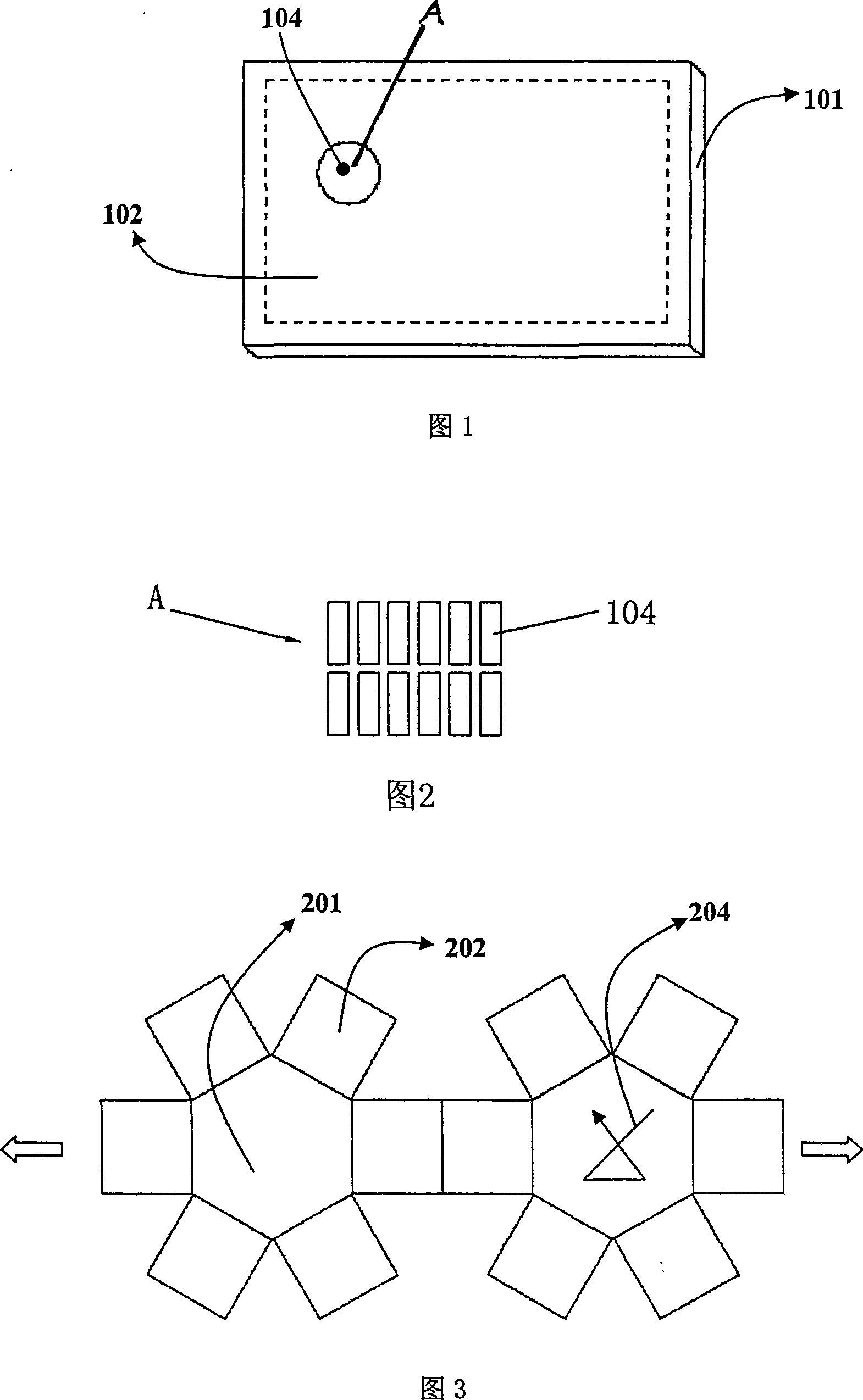
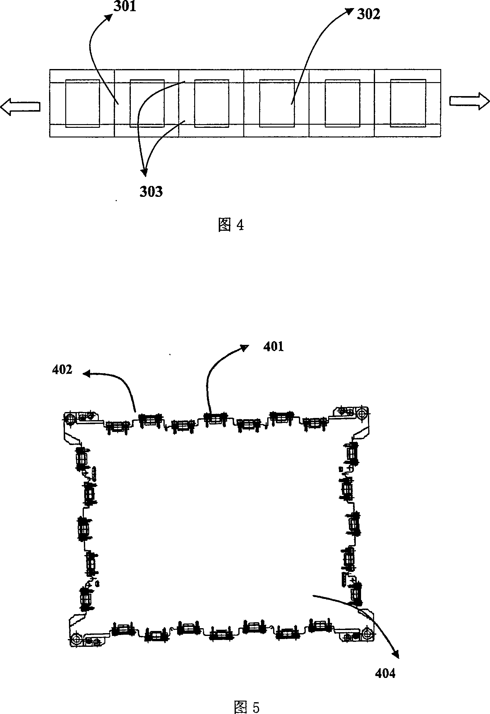
[0033] A linear organic light emitting display manufacturing system, the manufacturing system has a fixed mask plate holder 601 in its processing module. As shown in FIG. 7 and FIG. 8 , the mask plate holder 601 is fixed at the bottom of the processing module. The fixed mask holder 601 has a design of a square ring with a support platform 602 open on one side, that is, the mask holder 601 has a square ring with an open side, and the square ring of the mask holder 601 A support platform 602 for placing a mask plate is extended from the inner side of the ring. Except for changing the mask 102 , the mask 102 is always fixed in the square ring of the mask holder 601 . The function of the support table 602 is to hold the mask frame 101 .

[0034] A mask rolling pin 606 may also be provided on the support table 602 of the mask holder 601, and the mask rolling pin 606 helps the mask 102 to move in and out smoothly without generating rubbing debris or causing the frame to scratched....


PUM


Abstract

The invention relates to technique field of organic luminous display unit manufacture system, specially a linear type organic luminous display unit manufacture system. The invention uses immobilized mask plate fixing device, which fixes mask plate in square ring of the fixing device besides replacement of the mask plate. The entire system does not need load frames and relevant parts. This makes inner structure of module more simple, transmission fluency and quick, amount of modules fewer, so that finally cost of system becomes low, operation and system maintenance becomes easy. Because mask plate is permanently in combination with mask plate fixing device, contraposition is carried out on entity of component where mask plate is located, only glass substrate moves to component where mask plate is located and no other component moves, the contraposition is easy, fast and precise, and production efficiency is effectively improved.

Description

Technical field: [0001] The invention relates to the technical field of manufacturing systems for manufacturing organic light emitting displays, in particular to a manufacturing system for linear organic light emitting displays. Background technique: [0002] Organic light emitting displays have been regarded as a new generation of flat panel displays (FPDs) following the currently dominant liquid crystal displays (LCDs) or plasma displays (PDPs), one of the reasons for which is its simple device structure and thus simple manufacturing process, and its excellent image quality. Multi-layer thin films are successively deposited on the patterned ITO glass, starting from the hole injection layer (HIL) and the hole transport layer (HTL), followed by the red, green and blue three-color light-emitting layer (EML), the electron transport layer layer (ETL), electron injection layer (EIL), and finally the metal cathode layer. The thickness of each layer is in the nanometer (nm) level...

Claims


Application Information

Patent Timeline
Patent Type & Authority Applications(China)
IPC IPC(8): H05B33/10
Inventor 柳宗勋
Owner DONGGUAN ANWELL DIGITAL MASCH CO LTD
Learn More