
Turn signal switch device

A switch device and turn signal technology, applied in signal devices, electric switches, optical signals, etc., can solve the problems of reduced assembly efficiency and increased number of parts, and achieve the goal of improving assembly efficiency, controlling the number of parts, and simplifying assembly operations Effect

Active Publication Date: 2008-08-06
ALPS ALPINE CO LTD
View PDF2 Cites 0 Cited by
  • Summary
  • Abstract
  • Description
  • Claims
  • Application Information

AI Technical Summary

Problems solved by technology

But on the other hand, because must increase two parts of shaft 204 and fall-off prevention part 205, the number of parts is increased, and because very small fall-off prevention part 205 such as washer must be installed on one end of shaft 204 and occurred. Problems that reduce assembly efficiency

Method used


Image

  • Turn signal switch device
  • Turn signal switch device
  • Turn signal switch device

Examples


Embodiment Construction

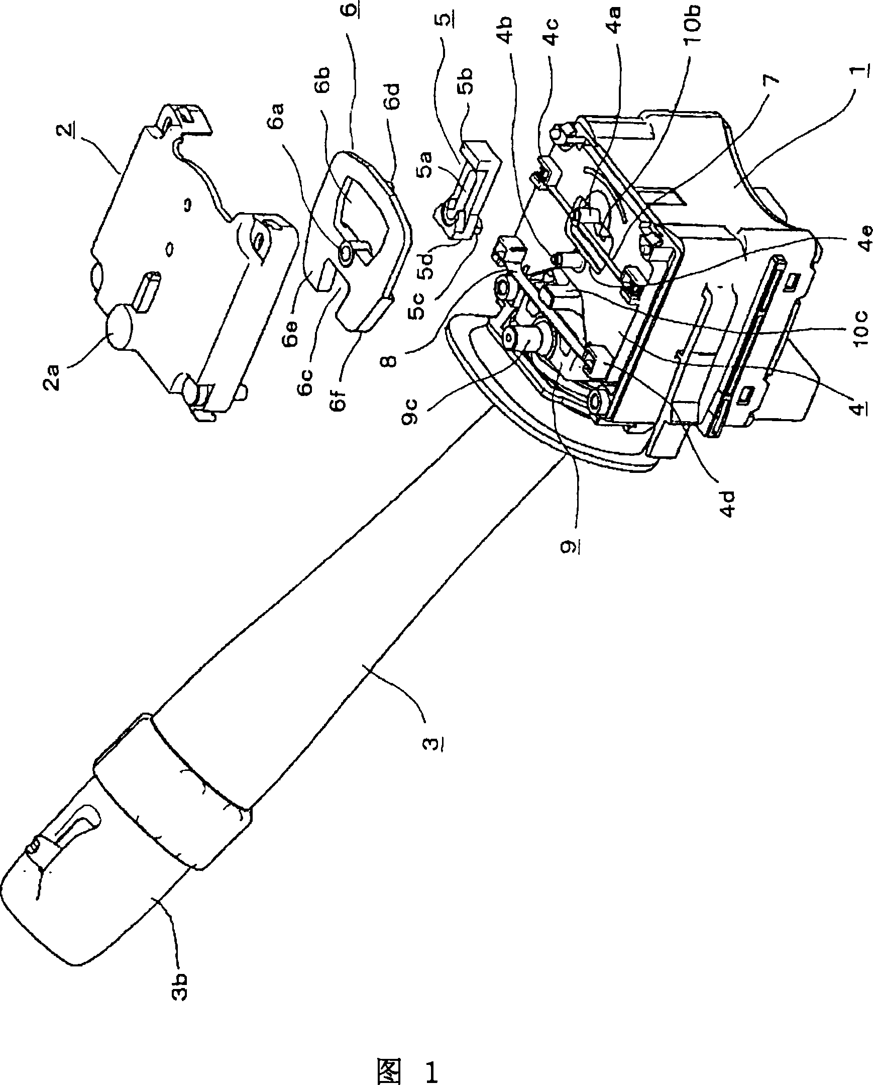
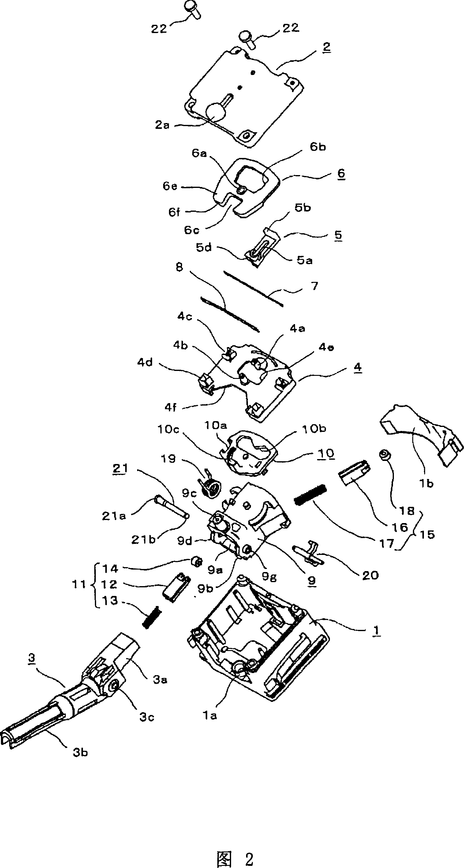
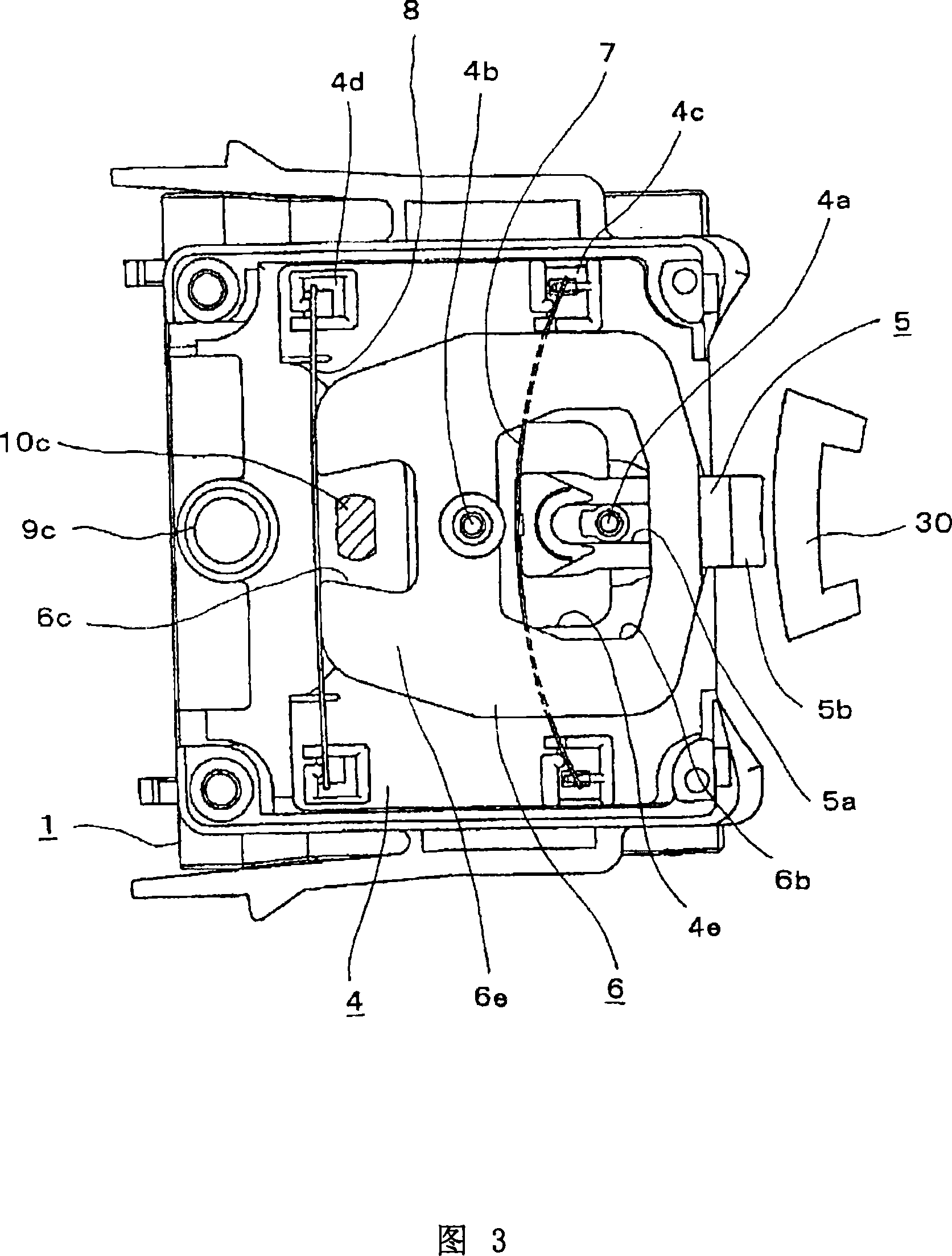
[0057] Hereinafter, specific embodiments of the present invention will be described with reference to the accompanying drawings. FIG. 1 is an external view showing a part of a turn signal switch device according to an embodiment of the present invention, FIG. 2 is an exploded perspective view of the turn signal switch device, and FIG. 3 shows a cancellation mechanism of the turn signal switch device. Fig. 4 is an explanatory diagram showing the state before the operation lever is automatically reset in the cancellation mechanism, and Fig. 5 is an illustration showing the shaft installation for connecting the base of the operation lever on the bracket 6 is an explanatory view showing a state where the installation work of the shaft has been completed, and FIG. 7 is an explanatory view showing a modified example of the bracket shown in FIG. 6 .

[0058] The turn signal switch device shown in these figures mainly includes: the first box part and the second box part forming the ca...


PUM


Abstract

The invention provides a turn signal switch device. Even if a control lever driven force is set with required strength, there's nothing to worry about the control lever base portion desquamation from a holder, assembly efficiency is fine and component amount can be reduced. When the turn signal switch device is assembled, a base portion (3a) of the control lever (3) is inserted into an opening (9a) of the holder (9), and a shaft (21) is inserted into a shaft hole (3c) of the base portion (3a) and a bearing hole (9e) of a side plate (9d) of the holder (9) so as to be retained. Then, the control lever (3) and the holder (9) are rotatably connected. Further, a ring-shaped groove (21b) is provided at the end of the shaft (21) opposite a head (21a), and a flexible engagement piece (9g) is provided on the side plate (9d) of the holder (9), the flexible engagement piece (9g) extending inward in the radial direction of the bearing hole (9e) so as to be engaged with the ring-shaped concave groove (21b). The flexible engagement piece (9g) is pressed and deflected by the leading end of the shaft (21) in the middle of attachment. Further, when the leading end passes through the flexible engagement piece (9g), the shaft (21) is snapped to the holder (9).

Description

technical field [0001] The present invention relates to a turn signal switch device attached to a steering column of an automobile and used as a direction indicator. Background technique [0002] In the turn signal switch device of an automobile, the base of the operating lever is pivotally supported by a bracket and can be tilted along a plane, and the bracket is pivotally supported by a housing fixed to a steering column, etc., so that the bracket and the operating lever are integrated and can be tilted along a plane The other plane, which is roughly orthogonal to the above-mentioned one plane, is poured. Then, if the rod portion of the operating lever is tilted from the neutral position to any one of the left and right direction indication positions along the above-mentioned other planes, the left turn or right turn light will flash. In addition, if the rod portion of the operating lever is tilted along the above-mentioned one plane, the light beam switching or overtakin...

Claims


Application Information

Patent Timeline
IPC IPC(8): H01H25/04B60R16/02H01H3/18
CPCB60Q1/425
Inventor 小坂谦
Owner ALPS ALPINE CO LTD
Learn More