
Polarization maintaining fiber beat length measuring apparatus

A polarization-maintaining optical fiber and measuring instrument technology, applied in the direction of measuring devices, optical instrument testing, instruments, etc., can solve the problems of complex structure, easy damage of optical fiber, and non-negligible impact, so as to simplify the composition structure, expand the application range, reduce The effect of design costs

Active Publication Date: 2008-08-06
CHINA NORTH IND NO 205 RES INST
View PDF1 Cites 13 Cited by
  • Summary
  • Abstract
  • Description
  • Claims
  • Application Information

AI Technical Summary

Problems solved by technology

However, the beat length tester still has the following problems: the force-applying mechanism is controlled by a magnet, and due to the existence of a close-range magnetic field, the influence of the magnetic field on the polarization state of the light in the polarization-maintaining fiber cannot be ignored; the force-applying mechanism is in direct contact with the optical fiber, The optical fiber is easy to be damaged; the polarization analyzer uses a fiber optic polarization device, and the polarization performance is not good enough; the optical system uses a collimator lens and an optical signal pre-processing module, and its structure is too complicated
The above problems all affect the measurement accuracy of the beat length measuring instrument, and bring inconvenience to the operation

Method used


Image

  • Polarization maintaining fiber beat length measuring apparatus
  • Polarization maintaining fiber beat length measuring apparatus
  • Polarization maintaining fiber beat length measuring apparatus

Examples


Embodiment Construction

[0022] The present invention will be further described in detail below in conjunction with the accompanying drawings and preferred embodiments.

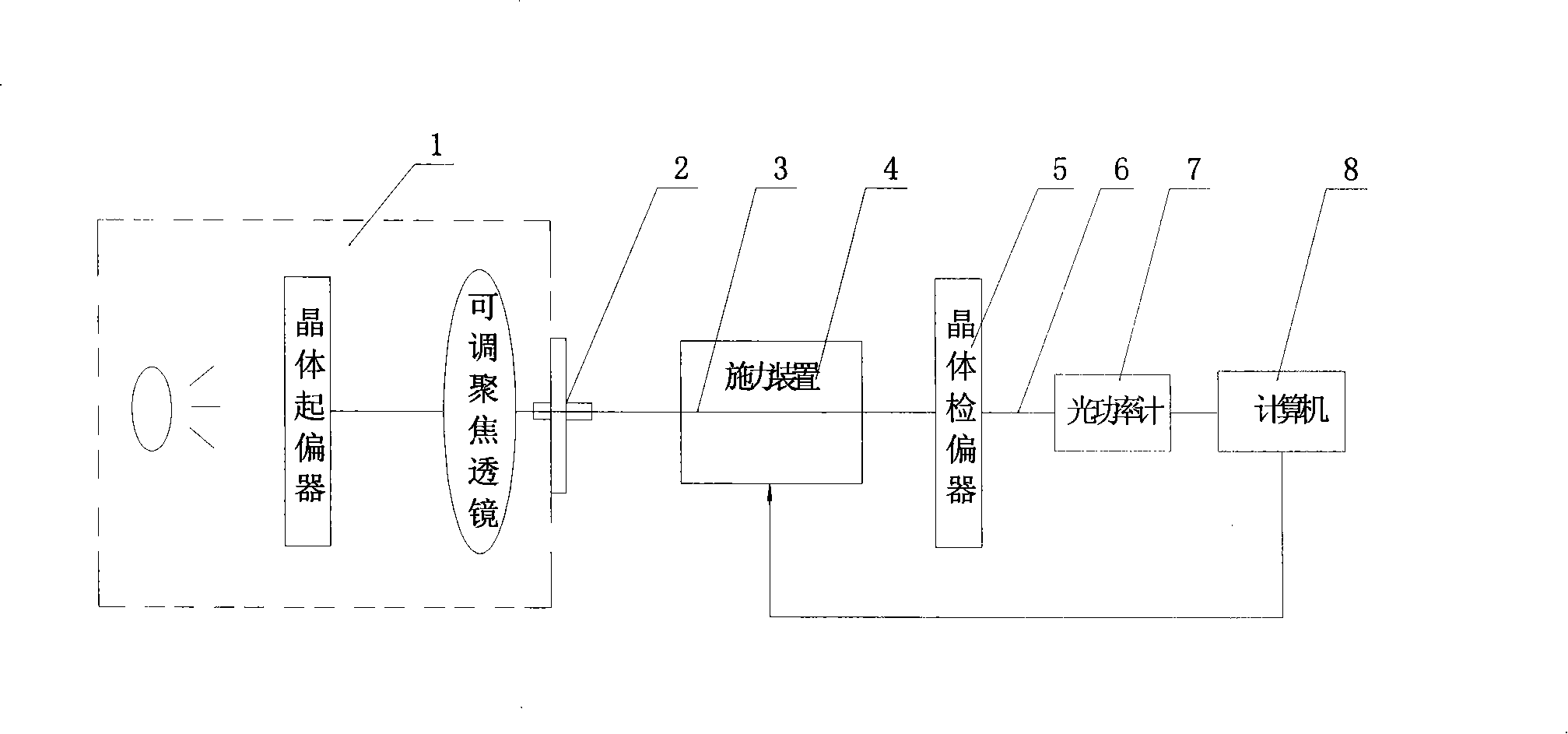
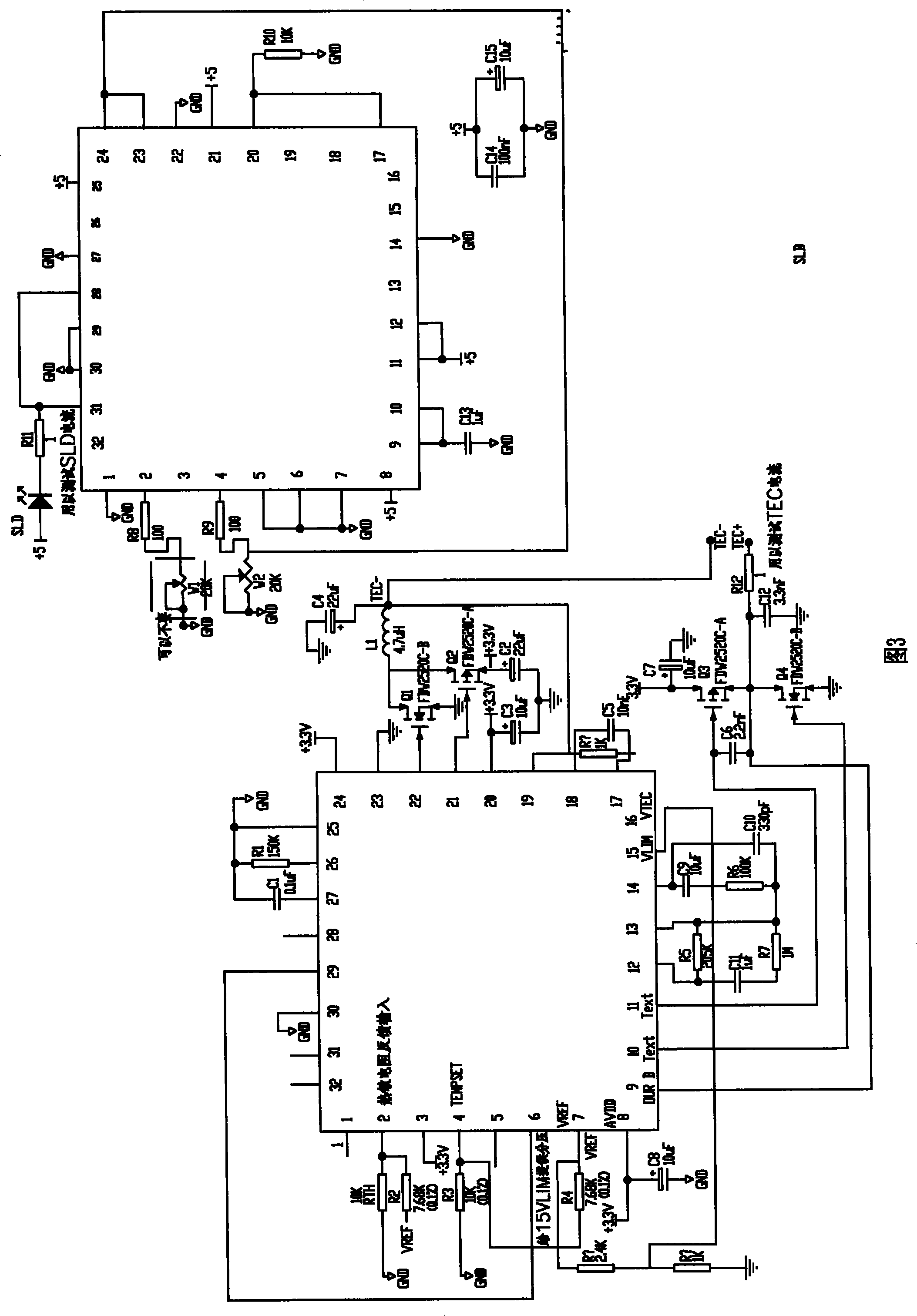
[0023] as figure 2 As shown, the preferred embodiment of the present invention includes an optical path system, a force applying device 4, and a data acquisition and processing system. The optical path system includes a light source, a crystal polarizer, a focusing lens, and a crystal analyzer. The light source, crystal polarizer, and focusing lens are individually integrated into an extinction ratio test device. The light source is composed of a semiconductor laser and a light source drive circuit. Through experimental analysis, it is found that the fluctuation of optical power is mainly determined by the ambient temperature and the constant current source. When the ambient temperature is within the refrigeration control range, the constant current source plays a major role. When the ambient temperature changes greatly, the latter...


PUM


Abstract

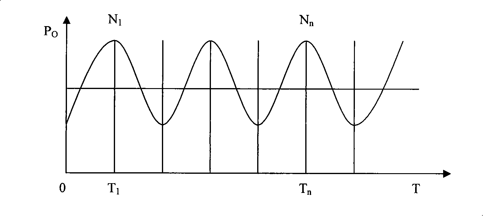
The invention discloses a polarization maintaining optical fiber beat length measuring apparatus, which comprises an optical path system, a force application device and a data acquisition and processing system. The optical path system containing a light source, a crystal polarizer, a focusing lens and a crystal polarization analyzer has the function of providing linearly polarized light for measurement; the force application device which adopts a travel mechanism with a high-precision bidirectional step motor, a clamp mechanism with protective measures, and a force application mechanism with a micrometer has the function of fixing a polarization maintaining optical fiber to be measured, applying a due radial pressure along the length direction of the polarization maintaining optical fiber to be measured in a mobile mode to enable the output optical power which has passed through the polarization maintaining optical fiber to be measured to have a periodical variation; the data acquisition and processing system picks up the optical power outputted by the measured optical fiber through an optical power meter and obtains the average beat length of the measured polarization maintaining optical fiber and the optical power variation curve with the acquisition time after a computer carries out corresponding processing and computation of the output of the optical power meter. The polarization maintaining optical fiber beat length measuring apparatus has the advantages of simple structure, convenient operation and high measurement precision.

Description

technical field [0001] The invention belongs to the technical field of inertial device measurement, and mainly relates to a polarization-maintaining optical fiber beat-length measuring instrument, in particular to a polarization-maintaining optical fiber beat-length measuring device with an extinction ratio test component as the core and the principle of a modulation pressure moving power method. technical background [0002] Polarization-maintaining fiber is a kind of single-mode fiber, which refers to the fiber whose core cross-section is deliberately elliptical, or which uses non-axisymmetric birefringence to transmit two orthogonal polarizations independently in an uncoupled manner. . Polarization-maintaining fiber is widely used in the field of fiber optic sensing, and its main applications include fiber optic gyroscopes, etc. Beat length is an important technical index of polarization maintaining fiber, which characterizes the birefringence performance of polarization...

Claims


Application Information

Patent Timeline
IPC IPC(8): G01M11/02G01M11/00
Inventor 郭栓运刘延虎黄皓袁晓莹扈宇姝尹剑李颖娟
Owner CHINA NORTH IND NO 205 RES INST
Learn More