
Ball-valve manufacture method

A manufacturing method and ball valve technology, applied in the field of ball valve manufacturing, can solve problems affecting industrial competitiveness, heavy overall quality, waste of water resources, etc., and achieve the effects of convenient production, sales, assembly and use, difficult chemical changes, and price increases

Inactive Publication Date: 2010-10-13
VALVE TEK MFG
View PDF4 Cites 0 Cited by
  • Summary
  • Abstract
  • Description
  • Claims
  • Application Information

AI Technical Summary

Problems solved by technology

[0003] Please refer to the Taiwan Patent No. 578871 "Structure Improvement of Ball Valve". Generally, ball valves must be made of metal to withstand water pressure for a long time and prevent wear and tear from water flow. It can be used as the opening and closing of water valves. Closed components, while ball valves made of metal materials have higher density and heavier overall quality, and in today’s world where various metal raw materials are in short supply and cost prices are rising, the price of ball valves is bound to soar, which will affect the competitiveness of the industry , or deter consumers, endure the shortcomings of water leakage or inaccurate opening and closing, and continue to use the ball valve that should be replaced, which will invisibly cause waste of water resources and inconvenience in life.
[0004] Because ball valves need to withstand water pressure and resist wear and tear, they are mostly made of metal materials, otherwise they will not be used if the damage rate is too high. Ball valves made of non-metallic materials, such as plastic materials or other materials, are generally prone to bacteria and impurities However, the high density of ball valves made of metal materials is not conducive to production, sales and assembly, and the high price of metal will also greatly increase the cost; therefore, the manufacturing and structure of ball valves There are actually dilemmas that need to be improved and overcome

Method used


Image

  • Ball-valve manufacture method
  • Ball-valve manufacture method
  • Ball-valve manufacture method

Examples


Embodiment Construction

[0046] The present invention relates to a manufacturing method of a ball valve, please refer to Figure 1 to Figure 10 As shown, the manufacturing method of this ball valve mainly includes the following steps:

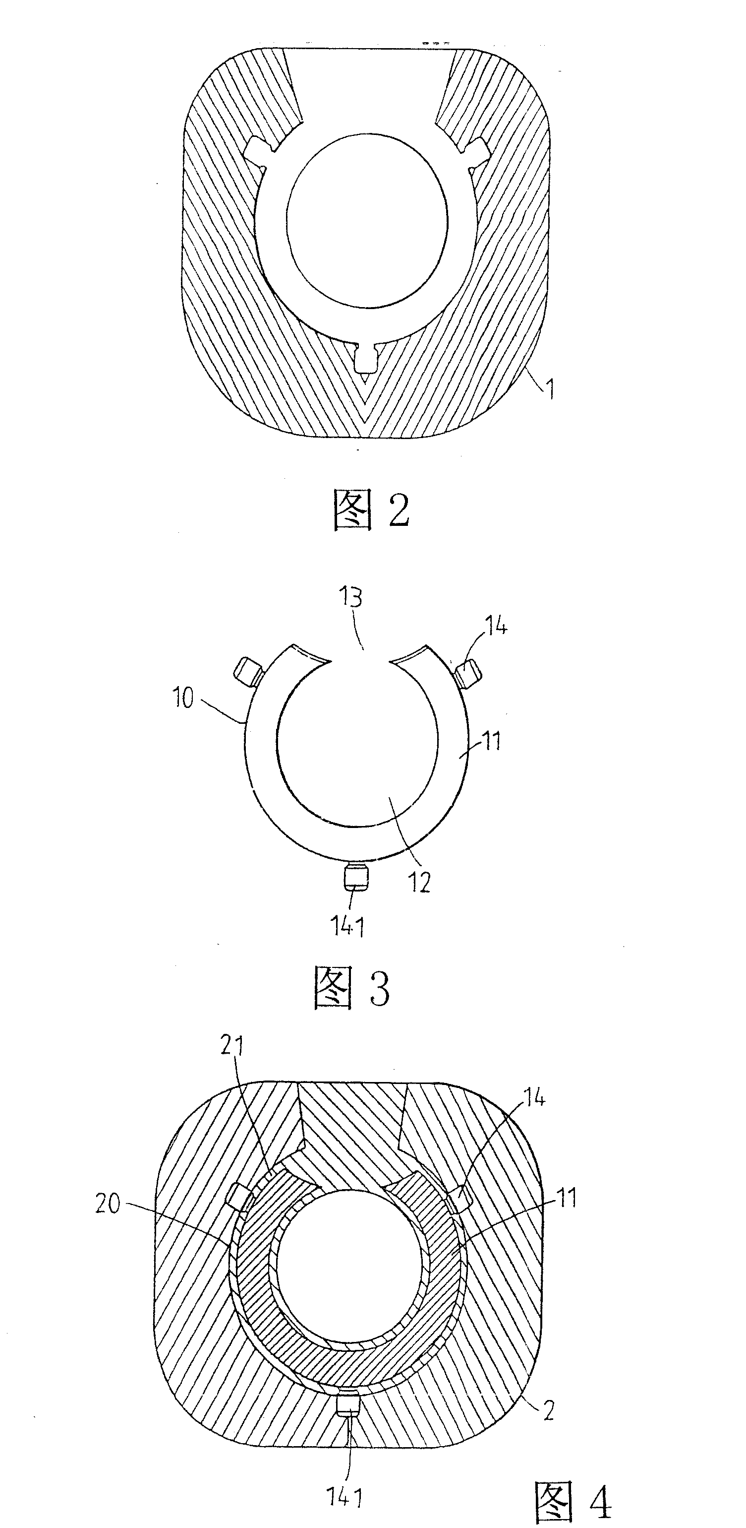
[0047] Modeling: such as figure 2 As shown, the first mold 1 of the corresponding size is selected according to the size of the ball valve to be manufactured, and then the raw materials whose main components are fire-resistant and heat-resistant materials such as magnesium oxide and aluminum oxide are poured into the first mold 1, and the mold is made as shown in FIG. image 3 The first base body 10 shown, the first base body 10 includes an arc-shaped inner filler 11, the inner filler 11 has a through hole 12 in the center, and the two ends of the inner filler 11 are separated by an opening 13 The outer side of the filling 11 is protrudingly provided with several positioning points 14 , at least one positioning point 14 is located on the axis of line symmetry of the ...


PUM


Abstract

Disclosed are a structure and a manufacturing method of a ball valve. The main technological process includes firstly producing a first base body made of flame-proof and heat-resistant materials with a first mold, then placing the first base body in a second mold, coating the first base body with a layer of wax surface with uniform thickness to form the second base body, producing a third mold bya method of making shell mold by slurry coating on the basis of the second base body, dewaxing the surface of the second base body, and filling metal liquid with high temperature in a third mold to form a third base body, wherein the third base body is composed of an external metal housing and internal nonmetal materials, then passing through the procedures of positioning point mending, sphericalsurface processing, ball track splitting, central point mending, surface burnishing and the like. Finally a ball valve which is light in weight, low in cost, good in intensity durability and not easyto cause chemical change is produced.

Description

technical field [0001] The invention relates to a manufacturing method of a ball valve. Background technique [0002] The ball valve is a component that controls the outlet valve of the water pipe. It has the function of opening and closing the water flow. In order to match the diameter of various water pipes, the ball valve also has various sizes. [0003] Please refer to the Taiwan Patent No. 578871 "Structure Improvement of Ball Valves". Generally, ball valves must be made of metal materials so as to withstand water pressure for a long time and prevent wear and tear from water flow. They can be used as opening and closing of water valves. Close components, while ball valves made of metal materials have higher density and heavier overall quality, and in today’s world where various metal raw materials are in short supply and cost prices are rising, the price of ball valves is bound to soar, which will affect the competitiveness of the industry , or deter consumers, endure ...

Claims


Application Information

Patent Timeline
Patent Type & Authority Patents(China)
IPC IPC(8): F16K5/06B22D25/02B22D7/00B22D9/00
CPCB22C9/101B22D19/00B22C9/04B22C7/02F16K27/067B22D19/06
Inventor 石超
Owner VALVE TEK MFG
Learn More