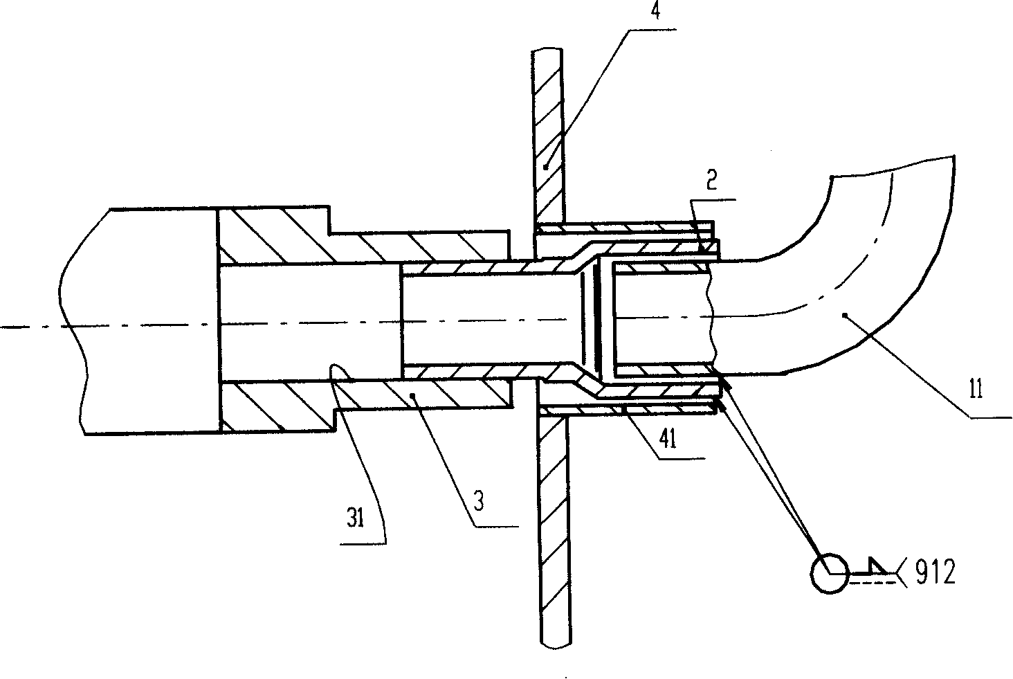
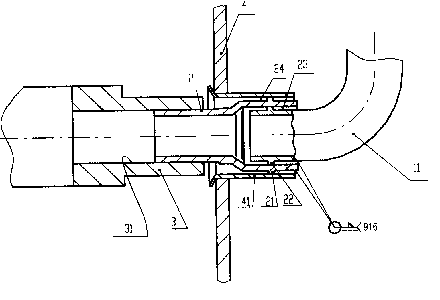
Totally-enclosed -type compressor suction duct connecting mechanism
A technology of connecting mechanism and compressor, applied in the direction of machine/engine, mechanical equipment, welding equipment, etc., can solve the problems of poor environmental protection effect, high production cost, low production efficiency, etc., achieve good welding effect, reduce production cost, improve The effect of welding performance
- Summary
- Abstract
- Description
- Claims
- Application Information
AI Technical Summary
Problems solved by technology
Method used
Image
Examples
no. 1 example
[0036] like image 3 Shown, design raised cylinder intubation annular band (21) in the middle of the inner and outer circle of big end of stepped cylinder insert (2), design the raised L-shaped tube annular band (22) at L-shaped tube (11) , the small end of the cylinder cannula (2) is pressed into the cylinder suction hole (31) with interference, the outer circle of the cylinder cannula ring (21) and the inner circle of the connecting pipe (41) have a clearance fit, and the radius clearance is 0.05~ 0.1 mm, the outer gap (24) of the cylinder cannula is designed as a reasonable welding gap, and its radial gap is 0.10-0.3 mm. The outer circle of the L-shaped pipe annular belt (22) is matched with the inner circle of the cylinder intubation pipe (2), the radial clearance is 0.05-0.1mm, and the outer clearance of the L-shaped pipe (23) is designed as a reasonable welding clearance, and the radial clearance is 0.10~0.3mm.
[0037] Figure 7 , 8 , 9 are derivative structures of ...
no. 2 example
[0040] like Figure 10 Shown: the clearance fit between the cylinder intubation tube (2) and the L-shaped pipe (11) and the connecting pipe (41) and the distribution of the annular band are the same as in the specific embodiment 1, the difference is that the inner annular band of the cylinder intubation tube (23) extends to the cylinder side with the outer annular band (24) of the cylinder intubation to each part hole or the excircle end, and guarantees the structure of the brazing gap. This design can bring two advantages. On the one hand, the processing and manufacturing are relatively simple; on the other hand, it is more conducive to ensuring the welding between the cylinder insert (2) and the L-shaped pipe (11) and the connecting pipe (41). Uniform distribution of gaps. In addition, the cylinder intubation pipe (2), the connecting pipe (41), and the L-shaped pipe (11) are all made of copper-plated steel on the surface.
[0041] Figure 11 , 12 , 13 is its derivative s...
no. 3 example
[0043] like Figure 14 As shown, since the L-shaped pipe (11) is inserted into the cylinder insert (2), it is much easier than the cylinder insert (2) to be pressed into the cylinder suction hole (31) through the inner hole of the connecting pipe (41), and welding The gap is relatively easy to reach evenly, so also can not produce the protruding annulus on the inner circle of the large end of the cylinder intubation pipe (2) or the outer circle of the L-shaped pipe (11). Only produce the protruding cylinder intubation annular band (21) on the outer circle of the cylinder intubation (2), the outer circle of the cylinder intubation annular band (21) fits with the inner hole clearance of the connecting pipe (41), and its radius The gap is 0.05 ~ 0.1mm, the outer gap (24) of the cylinder cannula is designed as a reasonable welding gap, the radius gap is 0.10 ~ 0.3mm, the distance between the L-shaped tube (11) and the inner hole of the cylinder cannula (2) It is designed to be a ...
PUM
 Abstract
Description
Claims
Application Information
 - R&D
- Intellectual Property
- Life Sciences
- Materials
- Tech Scout
- Unparalleled Data Quality
- Higher Quality Content
- 60% Fewer Hallucinations
Browse by: Latest US Patents, China's latest patents, Technical Efficacy Thesaurus, Application Domain, Technology Topic, Popular Technical Reports.
© 2025 PatSnap. All rights reserved.Legal|Privacy policy|Modern Slavery Act Transparency Statement|Sitemap|About US| Contact US: help@patsnap.com


