Dye sensitization solar cell module
A technology for solar cells and dye sensitization, applied in the field of dye-sensitized solar cell modules, can solve the problems of reducing the light utilization rate of transparent electrode forms, unfavorable cell production costs, complex internal structure of cells, etc. Reduced possibility, improved safety factor
- Summary
- Abstract
- Description
- Claims
- Application Information
AI Technical Summary
Problems solved by technology
Method used
Image
Examples
Embodiment 1
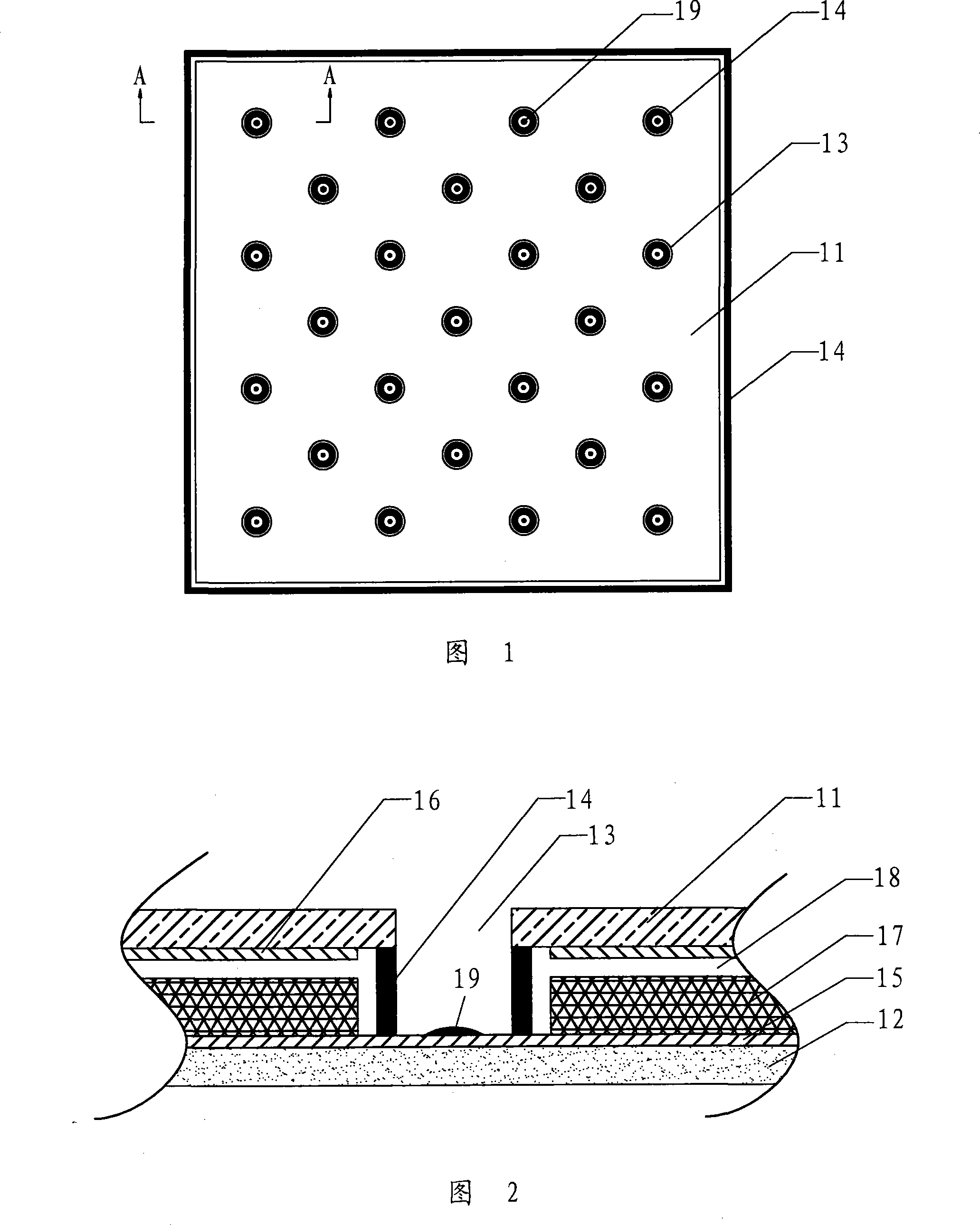
[0054] As shown in Figures 1 and 2, a dye-sensitized solar cell module includes: a first electrode and a second electrode, the first electrode includes an opaque substrate 11, and a catalyst layer 16 is arranged on one side of the working area of the opaque substrate 11, The material of the opaque substrate 11 is a kind of stainless steel plate, titanium plate, nickel plate, carbon plate, nickel-plated steel plate, nickel-plated iron plate, titanium-plated iron plate, titanium-plated steel plate, stainless steel plastic composite plate; the second electrode includes transparent Substrate 12, the transparent substrate 12 is covered with a conductive film 15, a nanoporous semiconductor film 17 is arranged on one side of the working area, the nanoporous semiconductor film 17 is impregnated with a photosensitive dye, and the material of the transparent substrate 12 is glass or transparent plastic.
[0055] The first electrode and the second electrode are arranged at intervals rel...
Embodiment 2
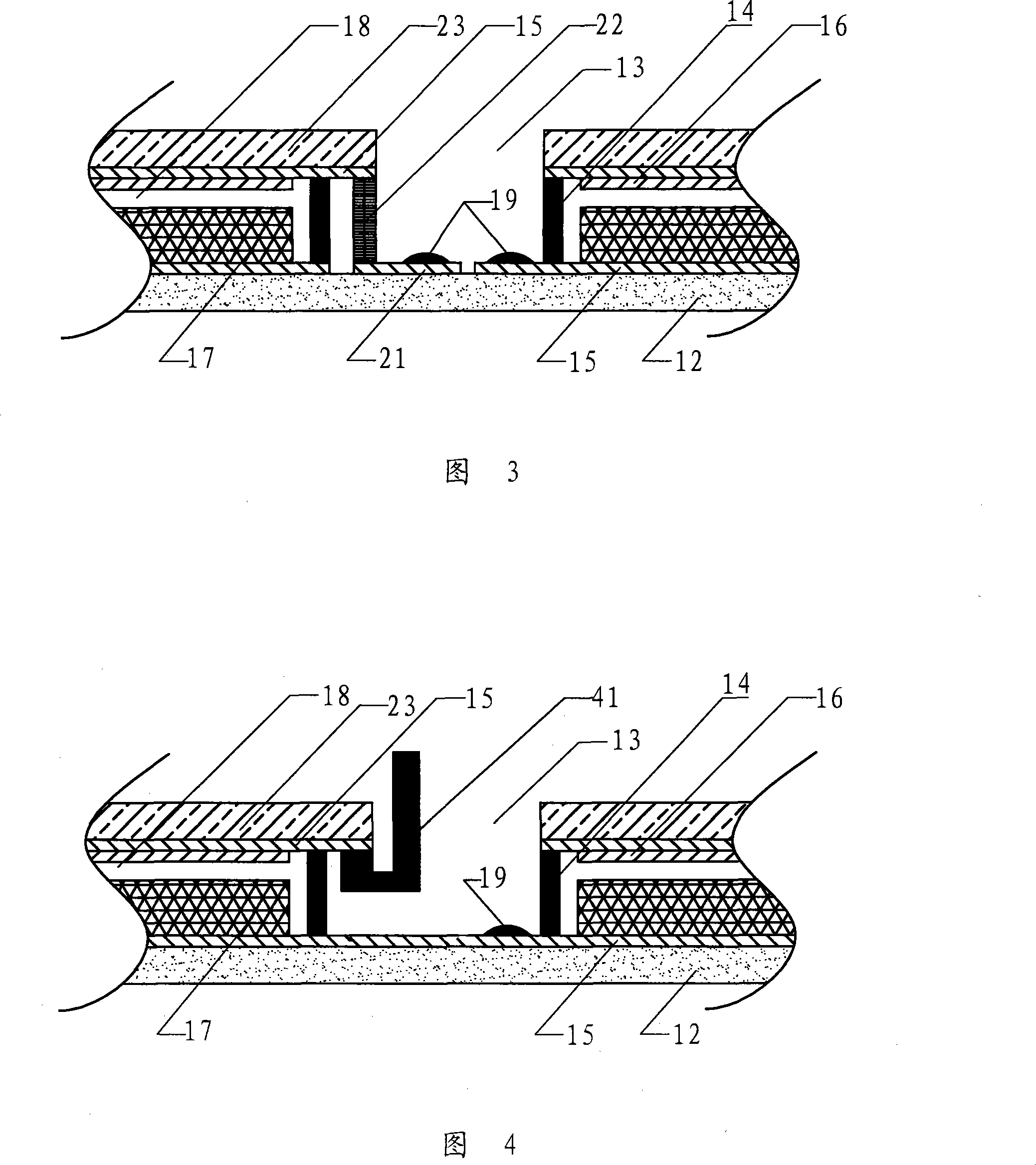
[0058] As shown in Figure 3, the structure of the battery module is basically the same as that of Embodiment 1, except that the first electrode and the second electrode are both transparent, and the material of the substrate 23 of the first electrode is transparent plastic or glass, and the first electrode is provided on the first electrode. Aperture 13, sealing material 14 seals with sealing material 14 around aperture 13; Adopt prior art to cut off conductive film 15 etching on substrate 12 in aperture to form conductive film isolated island 21, adopt conductive material 22 to connect conductive film isolated island 21 with the first The conductive film 15 on the first electrode substrate 11 is connected; the working current of the two electrodes is drawn out from the conductive film island 21 in the small hole and the second electrode current lead-out point 19 respectively.
Embodiment 3
[0060] As shown in Figure 4, the structure of the battery module is basically the same as that of Embodiment 1, except that the first electrode and the second electrode are both transparent, and the material of the substrate 23 of the first electrode is transparent plastic or glass, and the first electrode is set on the first electrode. Small hole 13, the periphery of small hole 13 is sealed with sealing material 14; the working current of the first electrode uses the conductor material 41 to directly draw the current from the small hole 13; the working current on the second electrode is drawn out through the current drawing point 19.
PUM
| Property | Measurement | Unit |
|---|---|---|
| electrical resistivity | aaaaa | aaaaa |
| thickness | aaaaa | aaaaa |
| thickness | aaaaa | aaaaa |
Abstract
Description
Claims
Application Information
 - Generate Ideas
- Intellectual Property
- Life Sciences
- Materials
- Tech Scout
- Unparalleled Data Quality
- Higher Quality Content
- 60% Fewer Hallucinations
Browse by: Latest US Patents, China's latest patents, Technical Efficacy Thesaurus, Application Domain, Technology Topic, Popular Technical Reports.
© 2025 PatSnap. All rights reserved.Legal|Privacy policy|Modern Slavery Act Transparency Statement|Sitemap|About US| Contact US: help@patsnap.com


